3 addressing of the process signals, 1 switch adjustments on vegacom 557, Addressing of the process signals – VEGA VEGACOM 557 Profibus FMS User Manual
Page 16: Bottom view of the component, Additional board bottom view
16
VEGACOM 557 Profibus FMS
Addressing of the process signals
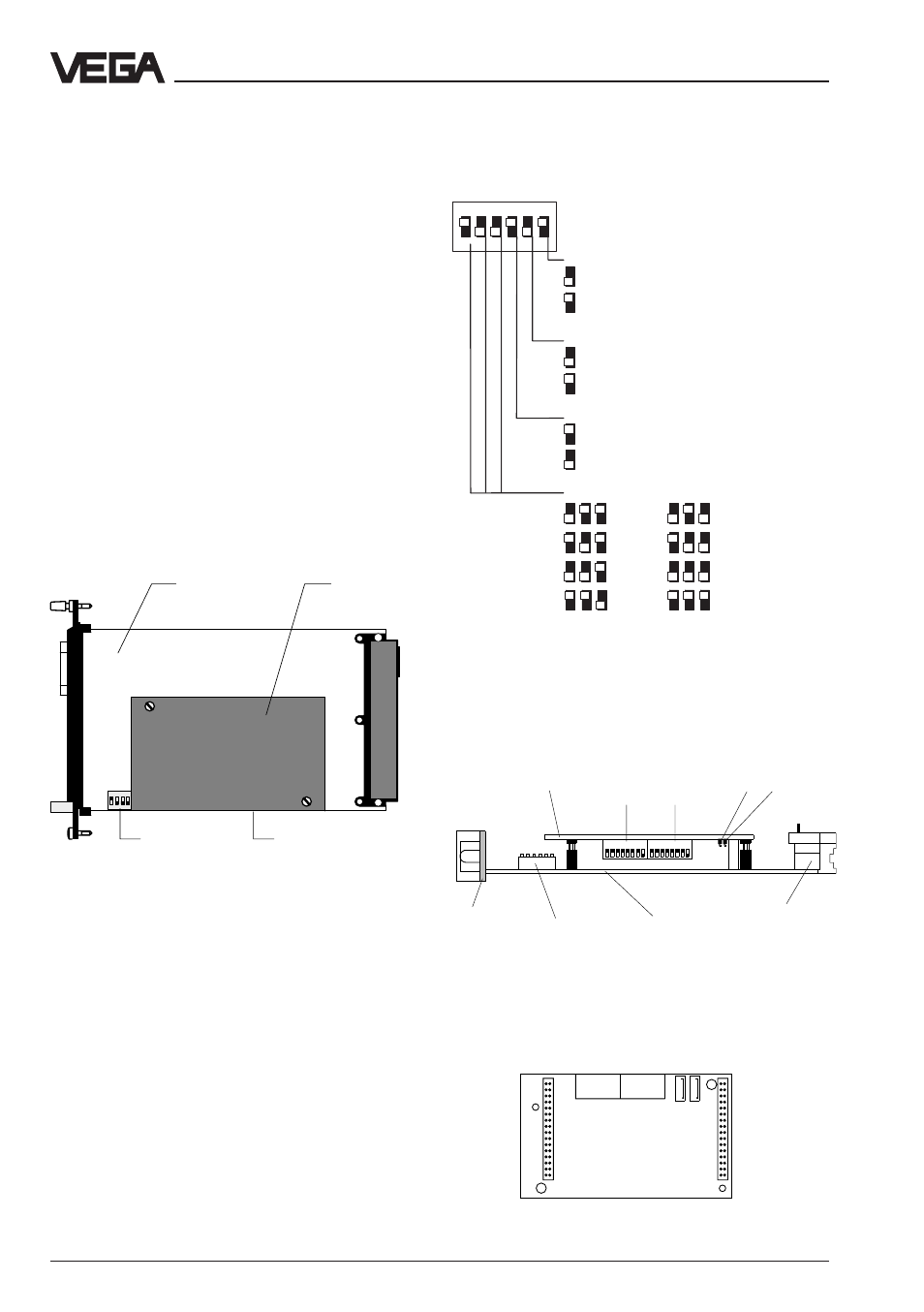
3.1 Switch adjustments on
VEGACOM 557
For adjustment of the RS 232 PC interface in
the front panel, a 6-pole DIL switch block is
located on the basic board. On the additional
board there are two 8-pole DIL switch blocks
as well as two hook switches for termination
of the bus.
Before inserting VEGACOM 557 into the
carrier or the housing, the DIL switches must
be set according to the user-specific data.
The data of this setting will take effect with the
next initialisation (switching on of voltage).
Side view of the component:
DIL switch, basic board
DIL switch, additional board
Bottom view of the component:
1 2 3 4 5 6 7 8
1 2 3 4 5 6 7 8
Additional
board
DIL switch
additional board
1
2
Hook switch
additional board
1
2
Multiple plug
Basic board
DIL switch
basic board
Front
plate
Additional board bottom view:
2
1
Hook switch
DIL switch
1
ON
EDG
2 3 4 5 6
Data format
8 data bits, 1 stop bit, even parity
8 data bit, 1 stop bit, no parity
Instrument number
1. instrument
2. instrument
Automatic modem initialisation
On
Off
Transmission rate (baud)
300
4800
600
9600
1200
19200
2400
38400
2 3 4
ON
1
Additional
board
DIL switch
on basic board
DIL switch
below additional
board
Basic board
Side view of VEGACOM 557
3 Addressing of the process signals
Factory setting