Function of the m&c jet-stream heat exchanger, Figure 2, Functioning diagram of the heat exchanger – M&C TechGroup ECP3000 Operator's manual User Manual
Page 8
8
Gas sampling and gas conditioning technology
3-1.1-ME
7
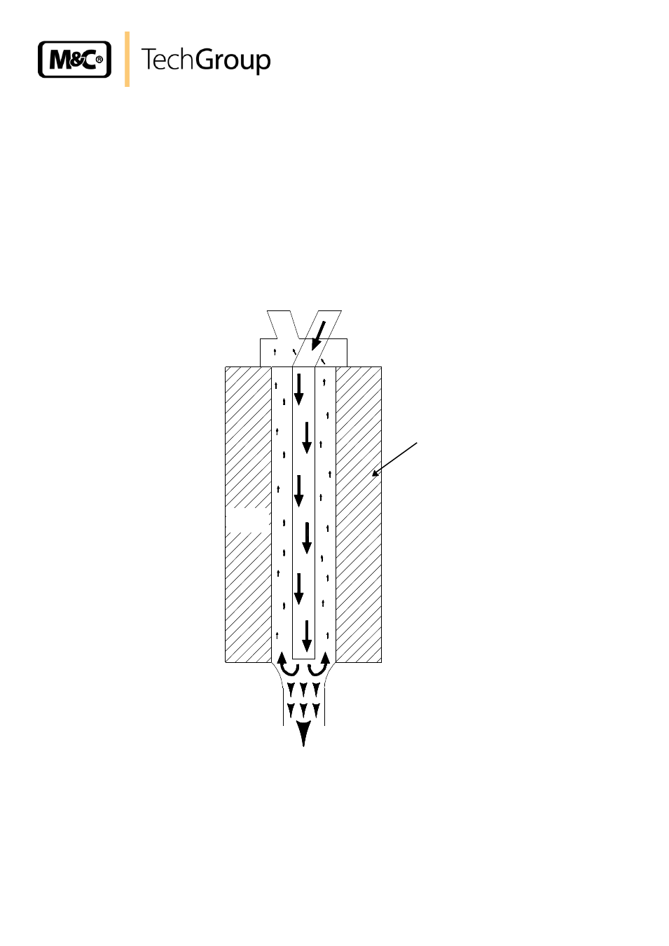
FUNCTION OF THE M&C JET-STREAM HEAT EXCHANGER
The coolers ECP 1000/2000/3000 with special design for analysis technique are prepared for
maximum flow rates of 350l/h.
The Jet-Stream heat exchangers made of Duran glass, optional PVDF or stainless steel are located in
a heat insulated cooling block. All the heat exchangers are easily accessible and are arranged in such
a way that they can be removed very simply. Figure 2 shows a schematic diagram of the functioning of
the heat exchanger.
+5°C
Sample gas
out
Sample gas
in
Condensate
out
Cooling-
block
Figure 2
Functioning diagram of the heat exchanger
See also other documents in the category M&C TechGroup Equipment:
- SP10 Operator's manual (14 pages)
- N9 KP18 Operator's manual (21 pages)
- SP2000_20SS 150 Data sheet (3 pages)
- SP3100 Data sheet (6 pages)
- PSP4000-H _C _T Data sheet (4 pages)
- SP2200-H_C_I_BB_F Data sheet (2 pages)
- SP35-H... for gas sample probe SP2000-H... Data sheet (2 pages)
- FP-BF Data sheet (2 pages)
- SP3200 Operator's manual (28 pages)
- FPF-0,1 Operator's manual (2 pages)
- PSS-10_1 Operator's manual (23 pages)
- CSS-V2 Data sheet (3 pages)
- PMA 50 EEX Operator's manual (48 pages)
- MP30 Operator's manual (18 pages)
- SP2600-H_C_I_BB_F_0,1GF190 Data sheet (3 pages)
- SR25.1_Ex Operator's manual (22 pages)
- PMA 10S Operator's manual (27 pages)
- CSS-M_W Data sheet (3 pages)
- PAS-500 Operator's manual (20 pages)
- SP2000H320_DIL... Data sheet (3 pages)
- SP3200 Data sheet (6 pages)
- FA-1_2_3,bi Operator's manual (24 pages)
- SR25 Data sheet (2 pages)
- SP3000 Data sheet (4 pages)
- PAS Series Data sheet (2 pages)
- CG Series Data sheet (2 pages)
- ECP 20-2 Data sheet (3 pages)
- MP30-EX Data sheet (2 pages)
- PSP4000-H_C_T Operator's manual (24 pages)
- DIL-U Data sheet (2 pages)
- ADS-So Data sheet (2 pages)
- VC-2-SL Operator's manual (18 pages)
- ECM-ExII Operator's manual (39 pages)
- MP12 Operator's manual (17 pages)
- FPF+ Data sheet (2 pages)
- KS 2.Ex Operator's manual (17 pages)
- PMA 50 EEX Data sheet (3 pages)
- PMA 10S Data sheet (3 pages)
- Gas Sample Probes Series SP Data sheet (2 pages)
- BA-C Operator's manual (16 pages)
- MV3_2-H Series Operator's manual (18 pages)
- VC-2-SL Data sheet (3 pages)
- FM-200K-H_FA Operator's manual (16 pages)
- SP 30-H.._EX2 Operator's manual (16 pages)
- SP2006-H280_DIL Operator's manual (35 pages)