Description, Figure 2 – M&C TechGroup PSS-5_3 Operator's manual User Manual
Page 9
9
Gas sampling and gas conditioning technology
4-2.1.1-ME
9
DESCRIPTION
Cooler
ECP
>°C
ON
<°C
EIN
Meßgas
AUS
AUS
Kondensat
max. 1800VA
GL18
GL25
11
255
540
440
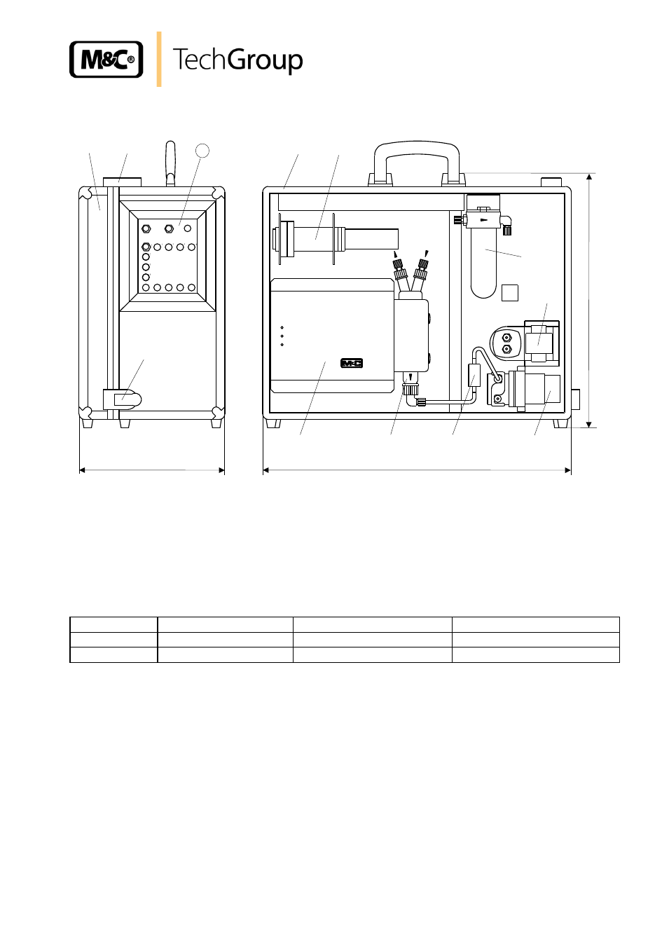
Figure 2
Design of the conditioning and sampling system PSS-5 and PSS-5/3
All the components of the gas conditioning system can be easily removed from the portable case 1 .
The door of the case 2 can be opened by moving the toggle-type fasteners 3 on the side and the top
to the left. The installation of a gas cooler 4 and an appropriate diaphragm gas pump 8 will be
carried out according to the maximum flow of gas extracted (see instruction manual for individual
components). The possible combinations are listed in the following table:
PSS-5...
Type of cooler
max. gas flow [Nl/h]
Sample gas pump
PSS-5
ECP1000
150
N 3 KPE
PSS-5/3
ECP3000
350
N 9 KPE
The minimum amount of flow is determined by the sample gas pump (see 15.). Premature damage
can be caused to the pump membrane if less than the minimal total amount of flow is extracted as a
result of excess pressure.
All gas coolers are equipped with a Borosilicate glass heat exchanger . Heat exchangers of PVDF
or stainless steel are also available.
The preliminary filter FP-2T (2 mm filter element fineness) installed in front of the gas measuring
pump 8 ensures that the correct amount of solid matter is precipitated. The sample gas pump is
turned off and on automatically by means of an excess temperature contact on the cooler (+8°C).
The resulting condensation is continually lead off by means of the SR25.1 9 peristaltic pump (s.
individual component instructions).
A preliminary filter, PF2 has been fitted in the condensation hose in between the heat exchanger
and peristaltic pump. This prevents particles in the condensate entering the pump.