Supply connections, Hose connections, N o t e – M&C TechGroup PSS-5_3 Operator's manual User Manual
Page 12
12
Gas sampling and gas conditioning technology
4-2.1.1-ME
12
SUPPLY CONNECTIONS
12.1
HOSE CONNECTIONS
N O T E !
Do not mix up the hose connections: they are clearly marked.
After all the hoses have been connected, the tightness of such
leads should be checked.
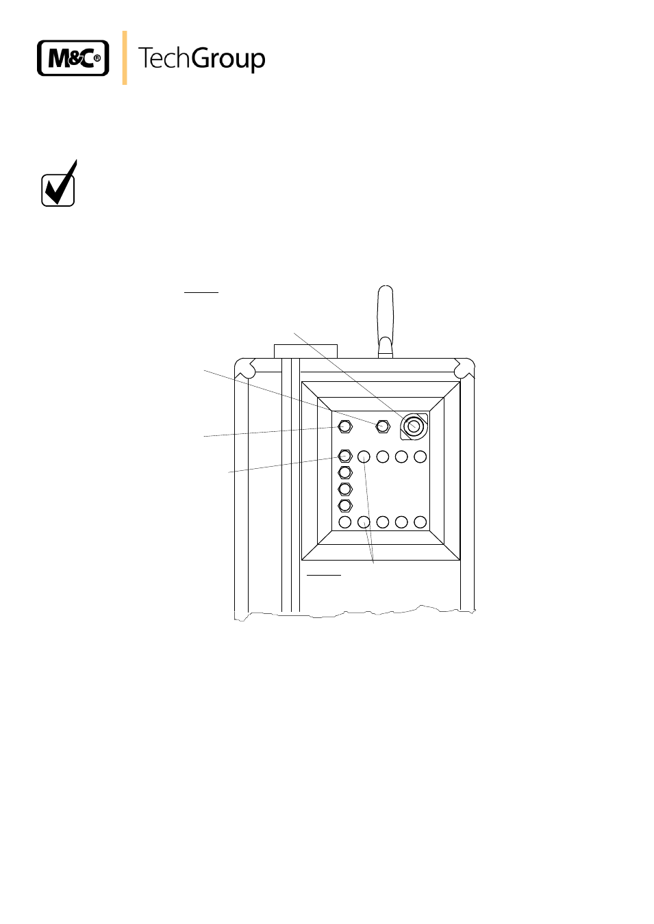
Figure 3 shows the possible medium connections. These are located in the right-hand side of the
gas conditioning case at the rear in a specially immersed assembly frame.
Option:
Mounting of max. 4 FM40
flowmeters possible
EIN
Meßgas
AUS
AUS
Kondensat
1
1
2
3
4
2
3
4
Condensate
Outlet
Sample gas
Outlet
(Option: max. 4)
Sample gas
Inlet
Option:
Electrical connection
for heated sample line
max. 6A, (230V/50Hz or 115V/60Hz)
All hose connections are equipped with 4/6mm sealing ring threaded hose couplings made of
polypropylene (PP) for gas input temperatures of up to a maximum of 80°C (see 8.). If heated
sample lines are used, whereby the gas input temperatures are increased up to a maximum of
180°C, additional bulkhead unions made of stainless steel are recommended.
Connection hoses with dimensions DN 4/6mm are utilised for all models.
The sample gas hoses, and condensation hoses, are to be assembled as follows:
Remove the union nut from the sealing ring couplings by turning it anti-clockwise. The nut should
be removed from the thread with great care so as to ensure that the loose sealing ring in the nut
is not lost.
Place the union nut over the connecting hose.