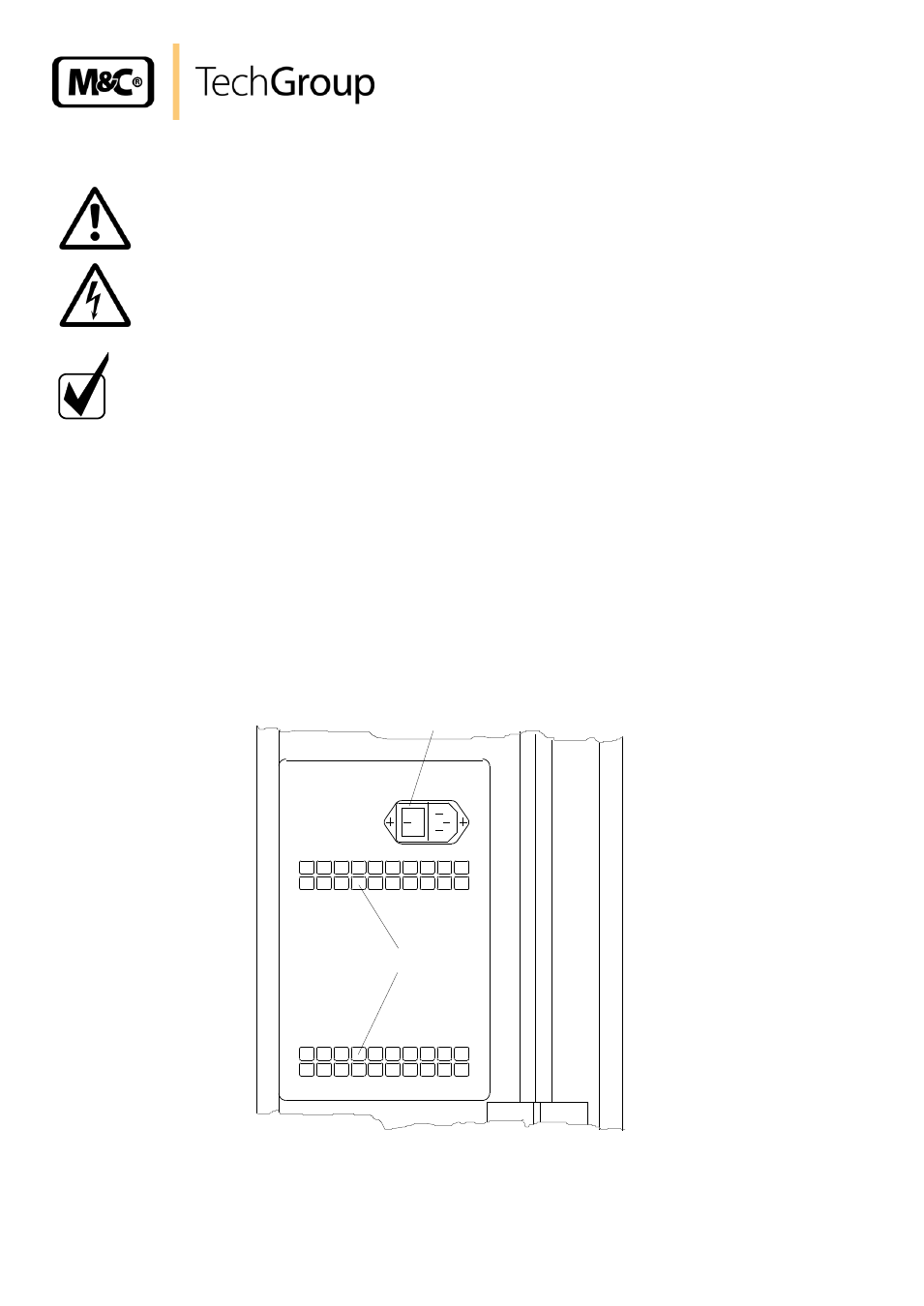
Electrical connections, Figure 3, Electrical connection and main switch – M&C TechGroup PSS-5_3 Operator's manual User Manual
Page 14: Ventilation grids
14
Gas sampling and gas conditioning technology
4-2.1.1-ME
12.2
ELECTRICAL CONNECTIONS
W A R N I N G !
False supply voltage can demage the equipment. When
connecting the equipment, please ensure tha the supply voltage
is identical with the information provided on the model type
plate !
N O T E !
For the erection of power installations with rated voltages up to
1000V, the requirements of VDE 0100 and relevant standards and
specifications must be observed!
The main circuit is equipped with a fuse corresponding to the
nominal current (over current protection); for electrical details
see technical data.
The PSS-5... gas conditioning system is available with either 230V/50 Hz or with 115V/60Hz (for
circuit diagram see Appendix). A 4A fuse is used on all models as fuse protection. The fuse is
located on the clamp mounting rail (see figure 2). In the event that a temperature controller is used
in conjunction with heated sample lines, the overload protection level is increased to 10A.
The electrical connection is carried out by means of a cold appliance plug and 2 m of cable located
on the left-hand side of the case. The cold appliance plug socket is equipped with two-polled main
switch.
Main switch and
cold appliance plug socket
0
Ventilation grids
Figure 3
Electrical connection and main switch