M&C TechGroup PSS-5_3 Operator's manual User Manual
Page 13
13
Gas sampling and gas conditioning technology
4-2.1.1-ME
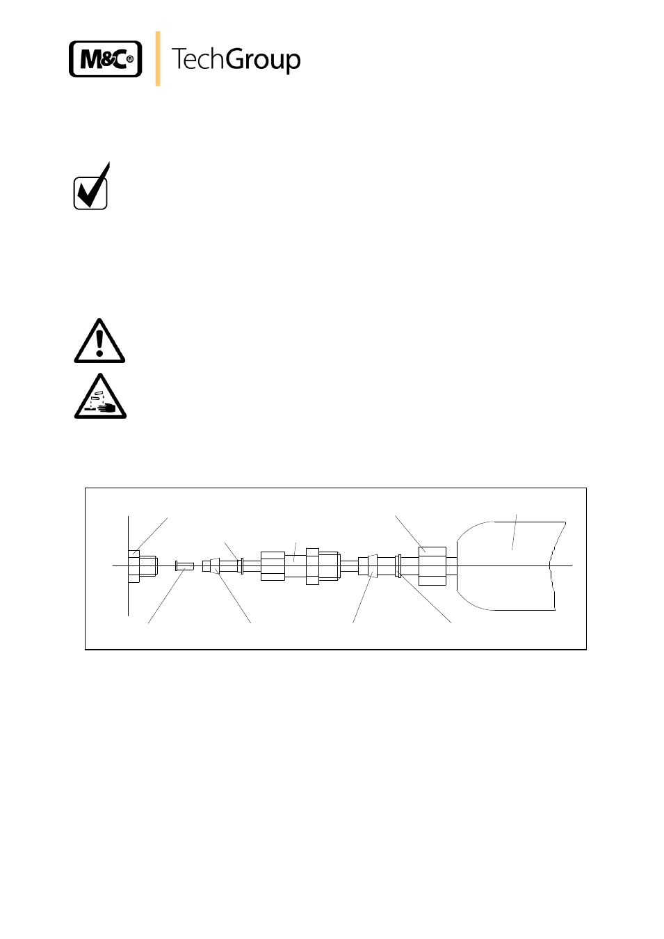
Sample gas IN
Bulkhead union
Back ferrule 6mm Øi
Back ferrule
10mm Øi
Sealing ring
10mm Øi
Sealing ring
6mm Øi
Insert
4mm Øo
Union nut 10mm Øi
Heated sample line
Adapter
PSS...
Place the sealing ring over the connecting hose with the thicker bead towards the nut.
Place the hose over the nipple on the thread.
N O T E !
The tightness of the connections can only be guaranteed if the
connecting hose has a straight rim (hose cutter).
The union nut is to be screwed tight by hand.
The hose will no longer be able to slip off, and is now compression-proof.
The hoses are to be removed in the reverse order.
W A R N I N G !
Aggressive condensate possible.
Wear protective glasses and proper protective clothing!
12.1.1 CONNECTING THE HEATED SAMPLE LINE WITH SPECIAL ADAPTER (OPTION)
Place the special adapter on the PTFE hose according to the drawing seen above;
Place the insert into the PTFE hose;
Place the PTFE hose over the nipple on the
bulkhead union ‘sample gas IN’ and screw the
adapter tight by hand;
Screw the adapter with a wrench (size 14) 1 1/4 rounds; for this fix the bulkhead union with a
wrench (size 15);
Place the 10mm tube of the heated sample line on the adapter and fix it by screwing the union
nut tight by hand;
Screw the union nut with a wrench (size 19) 1 1/4 rounds; for this fix the adapter with a
corresponding wrench;
Now the threaded joint is mounted tightness and can be loosen and fixed at any time.