Electrical installation, Figure 3, Dimensions (mm) mp06/12 – M&C TechGroup MP12 Operator's manual User Manual
Page 10: 2 electrical installation
10
Gas sampling and gas conditioning technology
6-1.1.10-ME
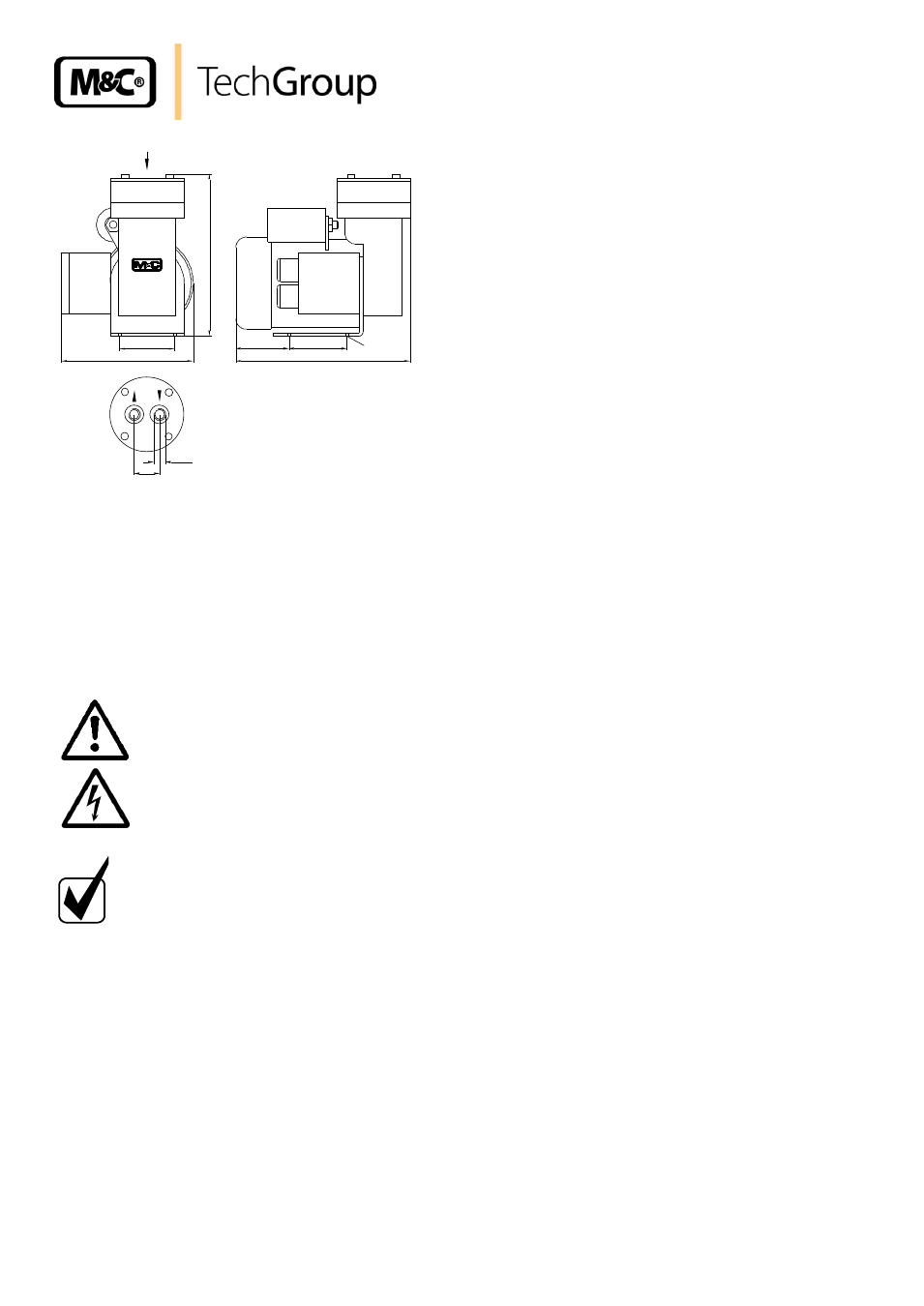
Figure 2
Dimensions (mm) MP06/12
10.2
ELECTRICAL INSTALLATION
The pumps MP06/12 is equipped with a mains cable with a plug as standard.
When making the electrical installation the safety regulations must be observed. In particular make
sure that the power supply is isolated before trying to connect the pump.
W A R N I N G !
When connecting the equipment, please ensure that the supply
voltage is identical with the information provided on the model
type plate.
The supply voltage is only allowed to deviate max. +6 % respec-
tively -10% from the indication on the model type plate.
N O T E !
Attention must be paid to the requirements of IEC 364 (DIN VDE
0100) when setting high-power electrical units with nominal volt-
ages of up to 1000 V, together with the associated standards and
stipulations.
Check the details on the type plate to ensure that the equipment is
connected up to the correct mains voltage. A main switch and
matching fuse must be provided externally! (EN 60335-1)
A protective motor switch is not necessary because the pump is
equipped with a thermal switch.
For electrical details see technical data.
In case the standard mains cable with plug should not be used, a wiring plan is in the cover of the
junction box.
The pump must be installed so that contact with live parts (connections, possibly windings) is im-
possible.
52
124
55
153
50
165
4xM4
G1/8"i
24
A
view A
Power in
230V 50Hz
MP 06/12
Dimensions in mm