Electrical connections, Figure 6, Electrical connection vc-1-sl – M&C TechGroup VC-2-SL Operator's manual User Manual
Page 13: Figure 7, Electrical connection vc-2-sl
13
Gas sampling and gas conditioning technology
3-0.1-ME
13.2
ELECTRICAL CONNECTIONS
C A R E !
When connecting the equipment, please ensure that the supply
voltage is identical with the information provided on the model type
plate!
N O T E !
Attention must be paid to the requirements of IEC 364 (DIN VDE
0100) when setting high-power electrical units with nominal
voltages of up to 1000V, together with the associated standards
and stipulations.
An external main switch must be provided.
The main circuit must be equipped with a fuse (over current
protection); for electrical details see technical data (chapter 8).
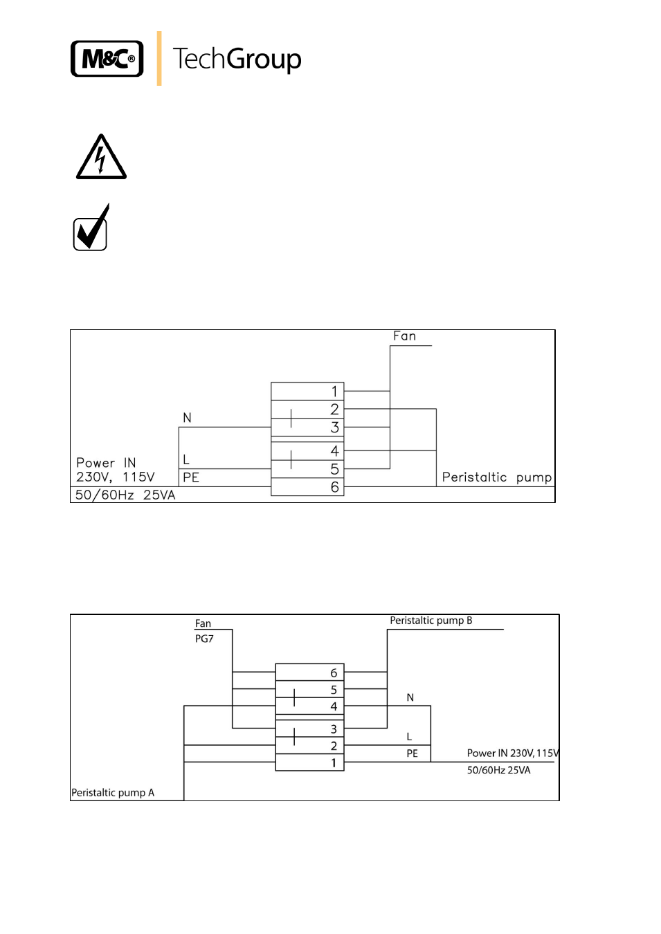
The electrical connection of the VC-1-SL is done in the housing of the peristaltic pump SR25.2-G:
Figure 6 Electrical connection VC-1-SL
The electrical connection of the VC-2-L is done in the connection box at terminals:
L = 3, N = 2 and PE = 1
The electrical connection of the VC-2-SL is done in the housing of the 2 peristaltic pumps SR25.1:
Figure 7 Electrical connection VC-2-SL