Figure 7, Transmitter unit – M&C TechGroup PMA 50 EEX Operator's manual User Manual
Page 32
32
Gas sampling and gas conditioning technology
9-3.15-ME
Pull off the green 2-, 3- and 4-pole plug-in connections from the power supply board;
Loosen the earth connection (green-yellow) of the transmitter unit (3 see figure.6);
Loosen the hex screws 4 (see figure 6) on the top of the transmitter mounting plate;
Loosen union nuts 1 at sample in- and outlet 7 (see figure 6);
Now, the complete transmitter unit can be taken out of the housing. All further procedures should be
executed on a clean work bench outside the hazardous area. Put the transmitter unit in a position as
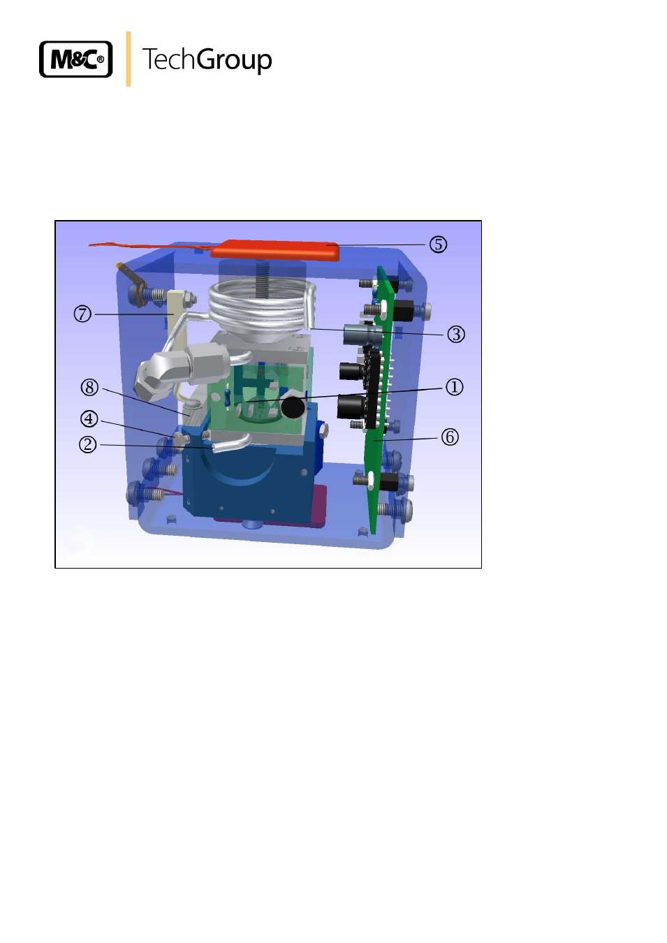
shown in figure 7 (18-pole plug must show to the right side).
Electrical connections meas. cell
Heater element
Gas outlet measuring cell
Transmitter board
Gas inlet measuring cell
Temperature cut out at 72
O
C
Fastening screw for measuring cell
Temperature sensor
Figure 7
Transmitter unit
Unsolder the brown and yellow cable from the terminals 1 (see figure 7) on the back side of the
measuring cell; do not overheat the terminals; mark the cables accordingly;
Disconnect the tubing for the sample gas outlet 2 and sample gas inlet 3;
Loosen the fastening screw of the measuring cell 4 with a screw driver and pick carefully the cell;
Exchange only with measuring cells of the same type;
Turn the transmitter as shown in figure 8 and loosen the fastening screw of the photocell 4.
The mountage of the measuring cell is to be effected in reverse order; take care of the correct dumpbell
position!
In case there are minimally different positions of the dumpbells inside the measuring cells when
mounting a new cell, it is absolutely necessary to adjust the zero point mechanically.