Bosch GCM 12 JL Professional User Manual
Page 35
English | 35
Bosch Power Tools
1 619 929 L91 | (6.8.12)
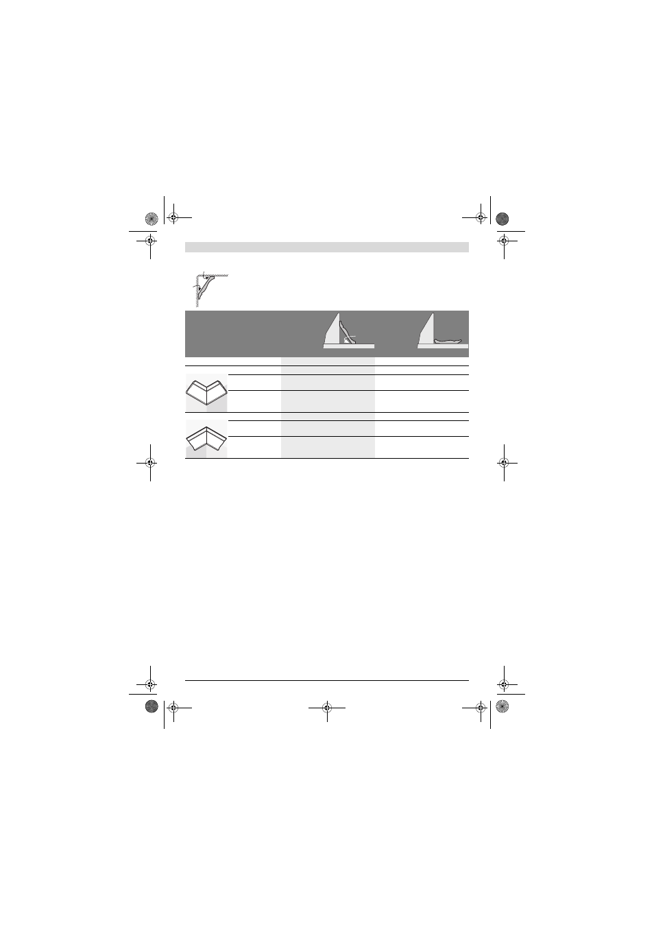
Ceiling Strips/Mouldings (According to US Standard)
Checking and Adjusting the Basic Adjustment
To ensure precise cuts, the basic adjustment of the machine
must be checked and adjusted as necessary after intensive
use.
A certain level of experience and appropriate specialty tools
are required for this.
A Bosch after-sales service station will handle this mainte-
nance task quickly and reliably.
Adjusting the Laser
Note: To test the laser function, the machine must be con-
nected to power.
f
While adjusting the laser (e. g. when moving the tool
arm), never actuate the On/Off switch. Accidental start-
ing of the power tool can lead to injuries.
– Bring the power tool into the working position.
– Turn the saw table 30 to the 0° detent 29. The lever 10
must be felt to engage in the detent.
– Switch the laser beam on with switch 31.
Checking: (see figure R1)
– Draw a straight cutting line on the workpiece.
– Press lever 22 and slowly guide the tool arm downward by
handle 4.
– Align the workpiece in such a manner that the teeth of the
saw blade are in alignment with the cutting line.
– Hold the workpiece in this position and slowly guide the
tool arm upward again.
– Clamp the workpiece.
The laser beam must be in alignment with the cutting line on
the workpiece over the complete length, also when the tool
arm is lowered.
Adjusting: (see figure R2)
– Screw the adjustment screw 55 in or out using a suitable
screwdriver until the laser beam is parallel with the cutting
line on the workpiece over the complete length.
One rotation in anticlockwise direction moves the laser beam
from left to right; one rotation in clockwise direction moves
the laser beam from right to left.
Setting the Standard Bevel Angle 0° (Vertical)
– Bring the power tool into the working position.
– Turn the saw table 30 to the 0° detent 29. The lever 10
must be felt to engage in the detent.
Checking: (see figure S1)
– Adjust an angle gauge to 90° and position it on the saw ta-
ble 30.
The leg of the angle gauge must be flush with the saw blade 37
over the complete length.
Adjusting: (see figure S2)
– Loosen clamping lever 23.
– Push the stop 26 completely to the rear.
– Loosen the lock nut of the stop screw 57 using a commer-
cial box-end or open-end spanner (size 13 mm).
– Screw the stop screw in or out until the leg of the angle
gauge is flush with the saw blade over the complete length.
When the ceiling strips/mouldings are to be sawn lying flat on the saw table, the standard mitre angles
of 31.6° (horizontal) and 33.9° (vertical) must be set.
The following table contains instructions for sawing ceiling strips/mouldings.
Settings
Placed
against the
fence
Lying flat on
the saw table
Bevel angle
0°
33.9°
Ceiling strip/moulding
Left side
Right side
Left side
Right side
Inner corner
Horizontal mitre angle
45° right
45° left
31.6° right
31.6° left
Positioning of work-
piece
Bottom edge
against the fence
Bottom edge
against the fence
Upper edge against
the fence
Bottom edge
against the fence
The finished work-
piece is located...
... to the right of the
cut
... to the left of the
cut
... to the left of the
cut
... to the left of the
cut
Outer corner
Horizontal mitre angle
45° left
45° right
31.6° left
31.6° right
Positioning of work-
piece
Bottom edge
against the fence
Bottom edge
against the fence
Bottom edge
against the fence
Upper edge against
the fence
The finished work-
piece is located...
... to the right of the
cut
... to the left of the
cut
... to the right of the
cut
... to the right of the
cut
52°
38°
52°
OBJ_BUCH-1600-002.book Page 35 Monday, August 6, 2012 3:36 PM