Assembly – Bosch GCM 12 JL Professional User Manual
Page 30
30 | English
1 619 929 L91 | (6.8.12)
Bosch Power Tools
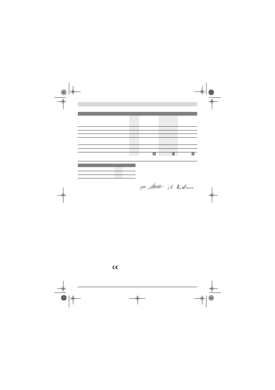
Technical Data
Noise/Vibration Information
Measured sound values determined according to EN 61029.
Typically the A-weighted noise levels of the product are:
Sound pressure level 98 dB(A); Sound power level
111 dB(A). Uncertainty K =3 dB.
Wear hearing protection!
Vibration total values a
h
(triax vector sum) and uncertainty K
determined according to EN 61029:
a
h
<2.5 m/s
2
, K=1.5 m/s
2
.
The vibration emission level given in this information sheet
has been measured in accordance with a standardised test
given in EN 61029 and may be used to compare one tool with
another. It may be used for a preliminary assessment of expo-
sure.
The declared vibration emission level represents the main ap-
plications of the tool. However if the tool is used for different
applications, with different accessories or poorly maintained,
the vibration emission may differ. This may significantly in-
crease the exposure level over the total working period.
An estimation of the level of exposure to vibration should also
take into account the times when the tool is switched off or
when it is running but not actually doing the job. This may sig-
nificantly reduce the exposure level over the total working pe-
riod.
Identify additional safety measures to protect the operator
from the effects of vibration such as: maintain the tool and the
accessories, keep the hands warm, organisation of work pat-
terns.
Declaration of Conformity
We declare under our sole responsibility that the product de-
scribed under “Technical Data” is in conformity with the fol-
lowing standards or standardization documents: EN 61029,
EN 60825-1 according to the provisions of the directives
2011/65/EU, 2004/108/EC, 2006/42/EC.
Technical file (2006/42/EC) at:
Robert Bosch GmbH, Dept. PT/ETM9,
D-70745 Leinfelden-Echterdingen
Robert Bosch GmbH, Power Tools Division
D-70745 Leinfelden-Echterdingen
Leinfelden, 22.06.2012
Assembly
f
Avoid unintentional starting of the machine. During as-
sembly and for all work on the machine, the power plug
must not be connected to the mains supply.
Delivery Scope
Carefully remove all parts included in the delivery from their
packaging.
Remove all packaging material from the machine and the ac-
cessories provided.
Before starting the operation of the machine for the first time,
check if all parts listed below have been supplied:
– Chop and mitre saw with mounted saw blade
– Dust bag 1
– Extraction adapter 2
– Material clamp 40
– Allen key 17
Note: Check the power tool for possible damage.
Before further use of the machine, check that all protective
devices are fully functional. Any lightly damaged parts must
be carefully checked to ensure flawless operation of the tool.
All parts must be properly mounted and all conditions fulfilled
that ensure faultless operation.
Damaged protective devices and parts must be immediately
replaced by an authorised service centre.
Chop and Mitre Saw
GCM 12 JL
Article number
3 601 M21 100
3 601 M21 130
3 601 M21 170
3 601 M21 160
3 601 M21 190
3 601 M21 1P0
Rated power input
W
2000
1500
1800
No-load speed
min
-1
4300
4300
4300
Reduced starting current
z
z
z
Laser type
nm
mW
650
< 0.39
650
< 0.39
650
< 0.39
Laser class
1M
1M
1M
Weight according to EPTA-Procedure 01/2003
kg
20.2
20.4
20.2
Protection class
/II
/II
/II
Permissible workpiece dimensions (maximal/minimal) see page 33.
The values given are valid for a nominal voltage [U] of 230 V. For different voltages and models for specific countries, these values can vary.
Dimension of suitable saw blades
Saw blade diameter
mm
305
Blade body thickness
mm
1.7–2.6
Mounting hole diameter
mm
30
Dr. Egbert Schneider
Senior Vice President
Engineering
Helmut Heinzelmann
Head of Product Certification
PT/ETM9
OBJ_BUCH-1600-002.book Page 30 Monday, August 6, 2012 3:36 PM