Maintenance and service – Bosch GCL 25 Professional User Manual
Page 15
English | 15
Bosch Power Tools
1 618 C00 50R | (9.7.12)
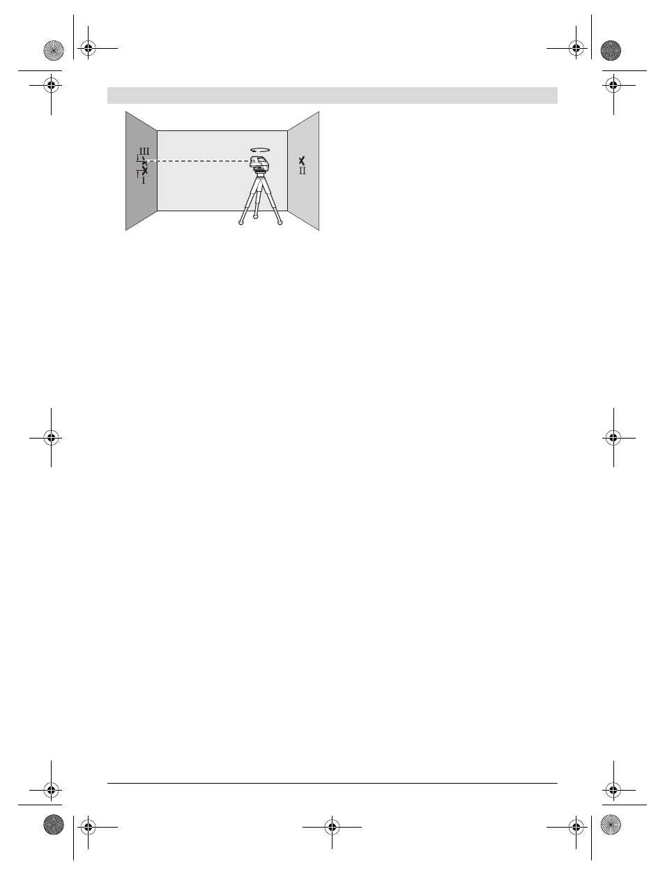
– Rotate the measuring tool by 180° without changing the
height. Allow it to level in and mark the centre point of the
laser beam on wall A (point III). Take care that point III is
as vertical as possible above or below point I.
– The difference d of both marked points I and III on wall A
results in the actual height deviation of the measuring tool
alongside the Longitudinal axis.
On the measuring distance of 2 x 20 m = 40 m, the maximum
allowable deviation is: 40 m x ±0.3 mm/m = ±12 mm.
Thus, the difference d between points I and III may not ex-
ceed 12 mm (max.).
Working Advice
f
For marking, always use only the centre of the laser
point or the laser line. The size of the laser point as well as
the width of the laser line change with distance.
Working with the Tripod (Accessory)
A tripod offers a stable, height-adjustable measuring support.
Position the measuring tool with the 1/4" tripod mount 7 onto
the thread of the tripod 16 or a commercially available cam-
era tripod. For fastening to a commercially available construc-
tion tripod, use the 5/8" tripod mount 6. Tighten the measur-
ing tool with the tripod mounting stud.
Adjust the tripod roughly before switching on the measuring
tool.
Fastening with the Universal Holder (Accessory)
With the universal holder 15, you can fasten the measuring
tool, e.g., to vertical surfaces, pipes or magnetizable materials.
The universal holder is also suitable for use as a ground tripod
and makes the height adjustment of the measuring tool easier.
Adjust the universal holder roughly before 15 switching on
the measuring tool.
Working with the Measuring Plate (Accessory)
(see figures A–B)
With the measuring plate 14, it is possible to project the laser
mark onto the floor or the laser height onto a wall.
With the zero field and the scale, the offset or drop to the
required height can be measured and projected at another
location. This eliminates the necessity of precisely adjusting
the measuring tool to the height to be projected.
The measuring plate 14 has a reflective coating that enhances
the visibility of the laser beam at greater distances or in
intense sunlight. The brightness intensification can be seen
only when viewing, parallel to the laser beam, onto the meas-
uring plate.
Working with the Laser Target Plate
The laser target plate 13 increases the visibility of the laser
beam under unfavourable conditions and at large distances.
The reflective part of the laser target plate 13 improves the
visibility of the laser line. Thanks to the transparent part, the
laser line is also visible from the back side of the laser target
plate.
Laser Viewing Glasses (Accessory)
The laser viewing glasses filter out the ambient light. This
makes the red light of the laser appear brighter for the eyes.
f
Do not use the laser viewing glasses as safety goggles.
The laser viewing glasses are used for improved visualisa-
tion of the laser beam, but they do not protect against laser
radiation.
f
Do not use the laser viewing glasses as sun glasses or in
traffic. The laser viewing glasses do not afford complete
UV protection and reduce colour perception.
Work Examples (see figures C – F)
Applicational examples for the measuring tool can be found
on the graphics pages.
Always position the measuring tool close to the surface or
edge subject to checking, and allow it to level in prior to each
measurement.
Always measure the distances between laser beam or laser
line and a surface or edge at two points as far as possible away
from each other (e.g. with the measurment plate 14).
Maintenance and Service
Maintenance and Cleaning
Store and transport the measuring tool only in the supplied
case.
Keep the measuring tool clean at all times.
Do not immerse the measuring tool in water or other fluids.
Wipe off debris using a moist and soft cloth. Do not use any
cleaning agents or solvents.
Regularly clean the surfaces at the exit opening of the laser in
particular, and pay attention to any fluff of fibres.
If the measuring tool should fail despite the care taken in man-
ufacturing and testing procedures, repair should be carried
out by an authorised after-sales service centre for Bosch
power tools. Do not open the measuring tool yourself.
In all correspondence and spare parts orders, please always
include the 10-digit article number given on the type plate of
the measuring tool.
For repairs, only send in the measuring tool in the case.
After-sales Service and Customer Assistance
Our after-sales service responds to your questions concern-
ing maintenance and repair of your product as well as spare
parts. Exploded views and information on spare parts can
also be found under:
www.bosch-pt.com
Our customer service representatives can answer your ques-
tions concerning possible applications and adjustment of
products and accessories.
d
180°
A
B
OBJ_BUCH-1546-002.book Page 15 Monday, July 9, 2012 10:30 AM