Bosch GCL 25 Professional User Manual
Page 14
14 | English
1 618 C00 50R | (9.7.12)
Bosch Power Tools
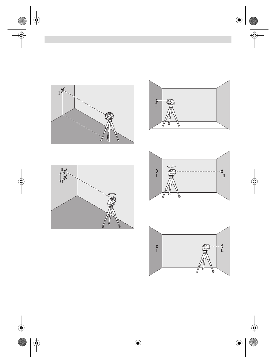
Checking the Horizontal Levelling Accuracy of the Lateral
Axis
A free measuring distance of 20 m on a firm surface in front of
a wall is required for the check.
– Mount the measuring tool onto the holder or a tripod, or
place it on a firm and level surface at a distance of 20 m to
the wall. Switch the measuring tool on and select 5-point
operation.
– Direct one of the two lateral laser beams, that run along-
side the lateral axis of the measuring tool, at the wall. Allow
the measuring tool to level in. Mark the centre of the laser
beam on the wall (point I).
– Rotate the measuring tool by approx. 180° without chang-
ing its height. Allow it to level in and mark the centre point
of the other lateral laser beam on the wall (point II). Take
care that point II is as vertical as possible above or below
point I.
– The difference d of both marked points I and II on the wall
results in the actual height deviation of the measuring tool
alongside the lateral axis.
On the measuring distance of 2 x 20 m = 40 m, the maximum
allowable deviation is:
40 m x ±0.3 mm/m = ±12 mm.
Thus, the difference d between points I and II may not exceed
12 mm (max.).
Checking the Horizontal Levelling Accuracy of the Longi-
tudinal Axis
A free measuring distance of 20 m on a firm surface between
two walls A and B is required for the check.
– Mount the measuring tool onto the holder or a tripod, or
place it on a firm and level surface close to wall A. Switch
the measuring tool on and select 5-point operation.
– Direct the horizontal laser beam, which runs parallel to the
longitudinal axis of the measuring tool, at the close wall A.
Allow the measuring tool to level in. Mark the centre of the
laser beam on the wall (point I).
– Turn the measuring tool around by 180°, allow it to level in
and mark the centre point of the laser beam on the oppo-
site wall B (point II).
– Without turning the measuring tool, position it close to wall
B. Switch the measuring tool on and allow it to level in.
– Align the height of the measuring tool (using the tripod or
by underlaying, if required) in such a manner that the cen-
tre point of the laser beam is projected exactly against the
previously marked point II on wall B.
20 m
d
180°
A
B
20 m
180°
B
A
A
B
OBJ_BUCH-1546-002.book Page 14 Monday, July 9, 2012 10:30 AM