Alarms, Process and deviation alarms, Alarm set points – Watlow Electric Integrated Controller User Manual Rev C EZ-ZONE PM User Manual
Page 65: Alarm hysteresis, Alarm latching
Wa t l o w E Z - Z O N E
®
P M I n t e g r a t e d C o n t r o l l e r
•
6 3
•
C h a p t e r 9 F e a t u r e s
Set Point
Time
Temperature
Temperature ramps to Set Point at a set rate
degrees
per minute
Alarms
Alarms are activated when the output level, process
value or temperature leaves a defined range. A user
can configure how and when an alarm is triggered,
what action it takes and whether it turns off auto-
matically when the alarm condition is over.
Configure alarm outputs in the Setup Page before
setting alarm set points.
Alarms do not have to be assigned to an output.
Alarms can be monitored and controlled through the
front panel or by using software.
Process and Deviation Alarms
A process alarm uses one or two absolute set points
to define an alarm condition.
A deviation alarm uses one or two set points that
are defined relative to the control set point. High
and low alarm set points are calculated by adding or
subtracting offset values from the control set point.
If the set point changes, the window defined by the
alarm set points automatically moves with it.
Select the alarm type with Type
[`A;ty] (Setup
Page, Alarm Menu).
Alarm Set Points
The alarm high set point defines the process value
or temperature that will trigger a high side alarm.
It must be higher than the alarm low set point and
lower than the high limit of the sensor range.
The alarm low set point defines the temperature
that will trigger a low side alarm. It must be lower
than the alarm high set point and higher than the
low limit of the sensor range.
View or change alarm set points with Low Set
Point
[`A;Lo] and High Set Point [`A;hi] (Operations
Page, Alarm Menu).
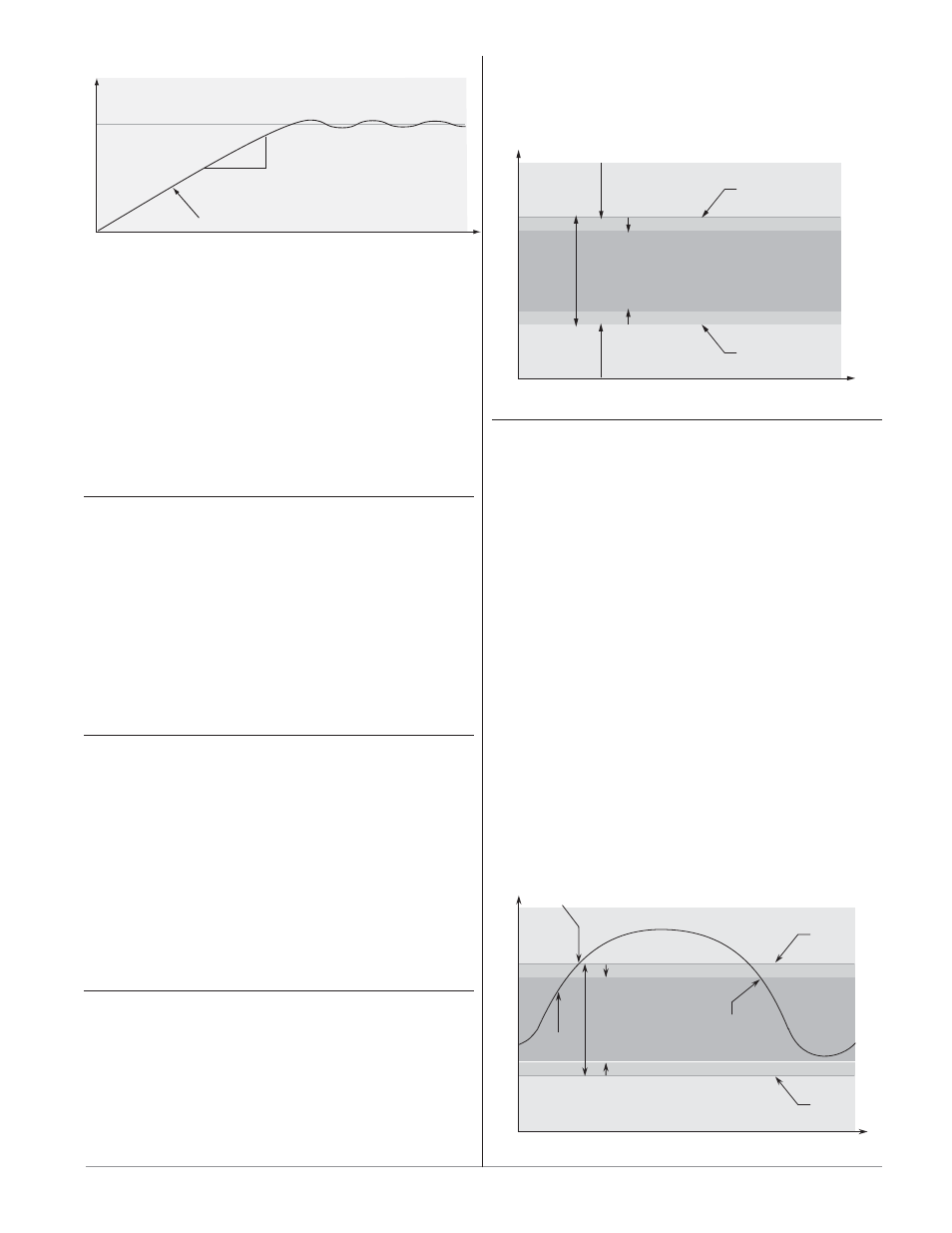
Alarm Hysteresis
An alarm state is triggered when the process value
reaches the alarm high or alarm low set point. Alarm
hysteresis defines how far the process must return
into the normal operating range before the alarm can
be cleared.
Alarm hysteresis is a zone inside each alarm set
point. This zone is defined by adding the hysteresis
value to the alarm low set point or subtracting the
hysteresis value from the alarm high set point.
View or change alarm hysteresis with Hysteresis
[`A;hy] (Setup Page, Alarm Menu).
Normal Operating Range
Low Side Alarm Range
High Side Alarm Range
Alarm High Set Point
Alarm Low Set Point
Time
Temperature
Alarm Hysteresis
Alarm Hysteresis
Alarm Latching
A latched alarm will remain active after the alarm
condition has passed. It can only be deactivated by
the user.
An active message, such as an alarm message,
will cause the display to toggle between the normal
settings and the active message in the upper display
and
[Attn] in the lower display.
Push the Advance Key to display
[ignr] in the
upper display and the message source in the lower
display.
Use the Up
¿ and Down ¯ keys to scroll through
possible responses, such as Clear
[`CLr] or Silence
[`SiL]. Then push the Advance ‰ or Infinity ˆ key
to execute the action.
See the Keys and Displays chapter and the Home
Page chapter for more details.
An alarm that is not latched (self-clearing) will
deactivate automatically when the alarm condition
has passed.
Turn alarm latching on or off with Latching
[`A;LA] (Setup Page, Alarm Menu).
Normal Operating Range
Alarm High
Set Point
Time
Temperature
Alarm Low
Set Point
The alarm state continues until the
temperature drops to the Alarm High
Set Point minus the hysteresis. A
latching alarm could be turned off by
the operator at this point. A non-
latching alarm would turn off
automatically.
The alarm state begins when the temperature
reaches the Alarm High Set Point
Process
Temperature
Alarm Hysteresis