Watlow Electric Integrated Controller User Manual Rev C EZ-ZONE PM User Manual
Page 36
Wa t l o w E Z - Z O N E
®
P M I n t e g r a t e d C o n t r o l l e r
•
3 4
•
C h a p t e r 6 S e t u p P a g e
To go to the Setup Page from the Home Page, press
both the Up
¿ and Down ¯ keys for six seconds.
[``Ai] will appear in the upper display and [`Set]
will appear in the lower display.
• Press the Up
¿ or Down ¯ key to move through
the menus.
• Press the Advance Key
‰ to move to a submenu.
• Press the Up
¿ or Down ¯ key to move through
the submenus.
• Press the Advance Key
‰ to move through the pa-
rameters of the menu or submenu.
• Press the Infinity Key
ˆ to move backwards
through the levels: parameter to submenu; sub-
menu to menu; menu to Home Page.
• Press and hold the Infinity Key
ˆ for two seconds
to return to the Home Page.
Note: Avoid continuous writes within loops. Excessive writes to
EEPROM will cause premature EEPROM failure. The EEPROM
is rated for 1,000,000 writes.
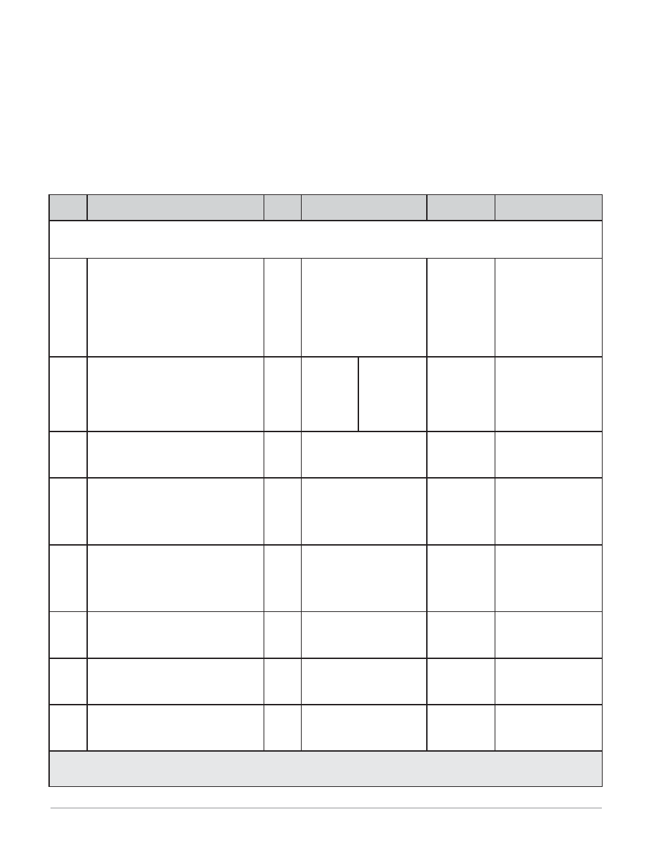
Dis-
play
Parameter Name
Description
Set-
tings
Range
Default
Appears If
[``Ai] [```1] [```2]
[`Set] [``Ai] [``Ai]
Analog Input Menu Analog Input 1 or
Analog Input 2
(input 2 appears if PM6 _ _ _ _-_ [R, T or L] _ _ A _ _)
[`Sen]
[ SEn]
Input (1 or 2)
Sensor Type
Set the analog sensor type to match the
device wired to this input.
Note: There is no open-sensor detection for
process inputs.
[`oFF] Off
[``tC] Thermocouple
[`mu] Millivolts
[uolT] Volts dc
[`MA] Milliamps dc
[r0;1H] RTD 100 Ω
[r1;0H] RTD 1,000 Ω
[`Pot] Potentiometer 1 kΩ
Thermocouple
always
[`Lin]
[ Lin]
Input (1 or 2)
Linearization
Set the linearization to match the thermo-
couple wired to this input.
[```b]
B
[```C]
C
[```d]
D
[```E]
E
[```F]
F
[```J]
J
[```H]
K
[```n]
N
[```r]
R
[```S]
S
[```t]
T
J
Sensor Type is set to
Thermocouple.
[`Rt;L]
[ rt.L]
Input (1 or 2)
RTD Leads
Set to match the number of leads on the
RTD wired to this input.
[```2]
2
[```3]
3
2
Sensor Type is set to
RTD 100 Ω or RTD
1,000 Ω.
[`S;Lo]
[ S.Lo]
Input (1 or 2)
Scale Low
Set the low scale for process inputs. This
value, in millivolts, volts or milliamps, will
correspond to the Range Low displayed by
the controller.
-100.0 to 1,000.0
0.0
Sensor Type is set to Mil-
livolts, Volts, Milliamps
or Potentiometer 1 kΩ.
[`S;hi]
[ S.hi]
Input (1 or 2)
Scale High
Set the high scale for process inputs. This
value, in millivolts, volts or milliamps, will
correspond to the Range High displayed by
the controller.
-100.0 to 1,000.0
20.0
Sensor Type is set to Mil-
livolts, Volts, Milliamps
or Potentiometer 1 kΩ.
[`r;Lo]
[ r.Lo]
Input (1 or 2)
Range Low
Set the low range for the displayed process
input units.
-1,999.000 to 9,999.000
0.0
Sensor Type is set to Mil-
livolts, Volts, Milliamps
or Potentiometer 1 kΩ.
[`r;hi]
[ r.hi]
Input (1 or 2)
Range High
Set the high range for the displayed pro-
cess input units.
-1,999.000 to 9,999.000
9,999
Sensor Type is set to Mil-
livolts, Volts, Milliamps
or Potentiometer 1 kΩ.
[`P;EE]
[ P.EE]
Input (1 or 2)
Process Error Enable
Turn the Process Error Low feature on or
off.
[`off] Off
[Low] Low
Off
Sensor Type is set to Mil-
livolts, Volts, Milliamps
or Potentiometer 1 kΩ.
Note: Some values will be rounded off to fit in the four-character display. Full values can be read with other interfaces.
If there is only one instance of a menu, no submenus will appear.