Tandberg Data T40 User Manual
Page 13
StorageLibrary Installation and User Guide
5
Issue operational commands.
View StorageLibrary status and information.
Test StorageLibrary functionality.
Control Buttons
The labels for the four control buttons are displayed in the corners of the LCD. All buttons have soft
function for different modes of operation, i.e. the functions of the buttons change during different
activities. The actual function for each button is always visible on the display.
LED Indicators
The two LED indicators are green and amber. They indicate the StorageLibrary activity as follows:
Green LED on: The StorageLibrary is either running or ready for operation.
Green LED blinking: Short blinks followed by long intervals indicate that the library is in low power
standby mode.
Amber LED on: Fault LED; the StorageLibrary has encountered an electrical or mechanical
failure.
Standby Switch
A switch on the front panel provides a Library Standby mode. If the switch is pushed when the library
is active, the library completes the current operation and then goes offline and enters standby mode.
See
Standby Functionality
for more details.
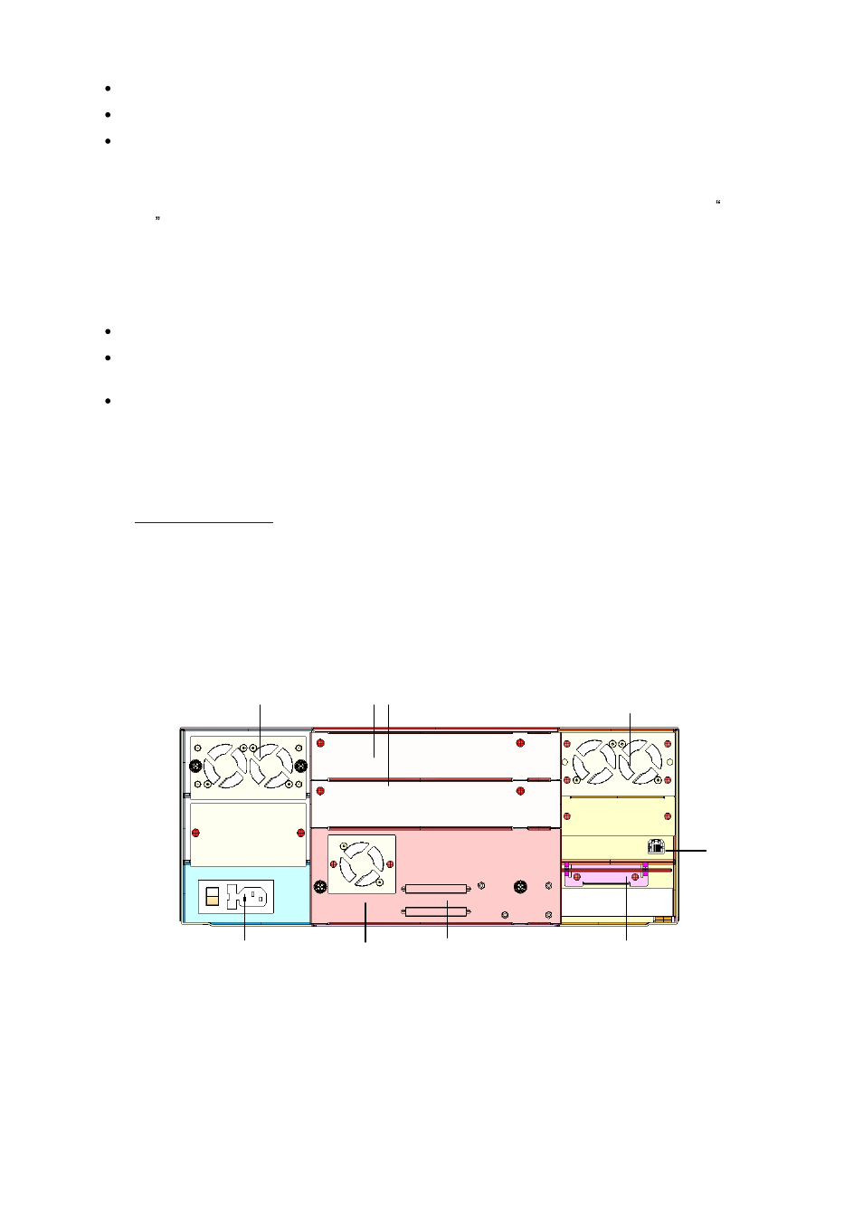
Rear Panel
The figure below shows the rear panel of the StorageLibrary.
Figure 2. Rear Panel of the StorageLibrary with 1 Full-Height SCSI Drive Installed
Cooling Fans
Forced-air cooling fans are integrated in both the power supply, the tape drive, and behind the library
control board. The fans draw air inward through holes in the front bezels and expel it out the back.
The fans start whenever the drive is operating or when the internal temperature in the StorageLibrary
gets too high.
Main power switch,
power outlet
and fuse
Back panel
cover plates
SCSI
connectors
Emergency eject tool.
(RTC battery and drive
power extension cable
behind cover.)
Ethernet
connector
Tape drive
with fan
Power supply
with fans
Cooling fans