Connecting the station wires – Toro 12 User Manual
Page 80
MV/
PUMP
1 2 3 4 5 6 7 8 9 10 11 12
MV/
PUMP
1 2 3 4 5 6 7 8 9 10 11 12
VC/
COM
VC/
COM
13 14 15 16 17 18 19 20 21 22 23 24
VC/
COM
37 38 39 40 41 42 43 44 45 46 47 48
37 38 39 40 41 42 43 44 45 46 47 48
25 26 27 28 29 30 31 32 33 34 35 36
25 26 27 28 29 30 31 32 33 34 35 36
VC/
COM
VC/
COM
VC/
COM
VC/
COM
13 14 15 16 17 18 19 20 21 22 23 24
VC/
COM
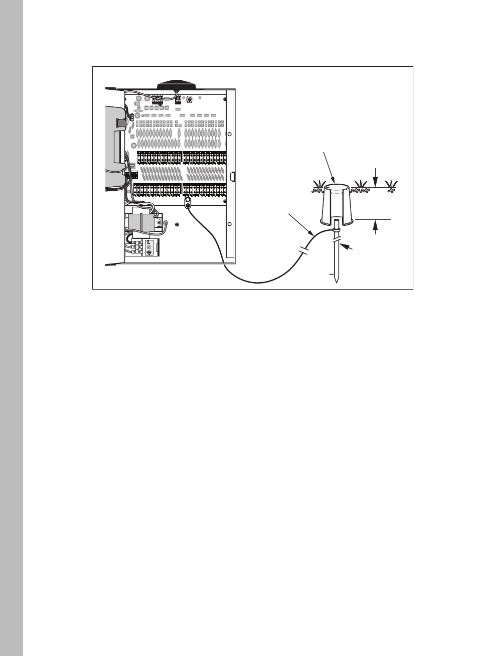
Connecting the Station Wires
74
1. To provide a valve common connection, interconnect one control
wire (generally white) to either lead of each valve solenoid.
2. Connect a separate control wire to the remaining lead of each
valve solenoid. For reference, note the wire color used for each
valve connection, it’s corresponding watering zone and the
intended station number.
3. If a master valve or pump start relay is used, make this connection
in the same manner.
4. Route the control wires into the controller cabinet through the
large opening provided or through conduit if installed.
5. Cut wires back as necessary to provide an appropriate length for
connection. Strip 3/8”(10mm) insulation from each wire.
4. Insert the ground wire into the copper ground lug and tighten
securely.
Ground Rod
12" (30.5cm)
Valve Box
6 AWG Solid
Copper Wire
Note:
Using 18 AWG (or larger) irrigation valve connection cable or
wire is recommended for all field wire connections.