Toro 12 User Manual
Page 78
72
Mounting the Controller
1. Open the cabinet door and TM mounting plate. Position the
controller on the wall and mark the top mounting hole location.
2. Install the top mounting screw leaving the screw head about
1/8" (3 mm) from the wall.
Note:
When installing the controller on masonry or dry wall, install
appropriate screw anchors.
3. Hang the controller on the screw. Install the lower mounting screw
and tighten both screws to ensure the controller is securely fastened.
Installing Conduit
Note:
Electrical conduit and adapters are not supplied with the controller
but may be required for installation in your area. Check local electrical
codes and install conduit according to requirements.
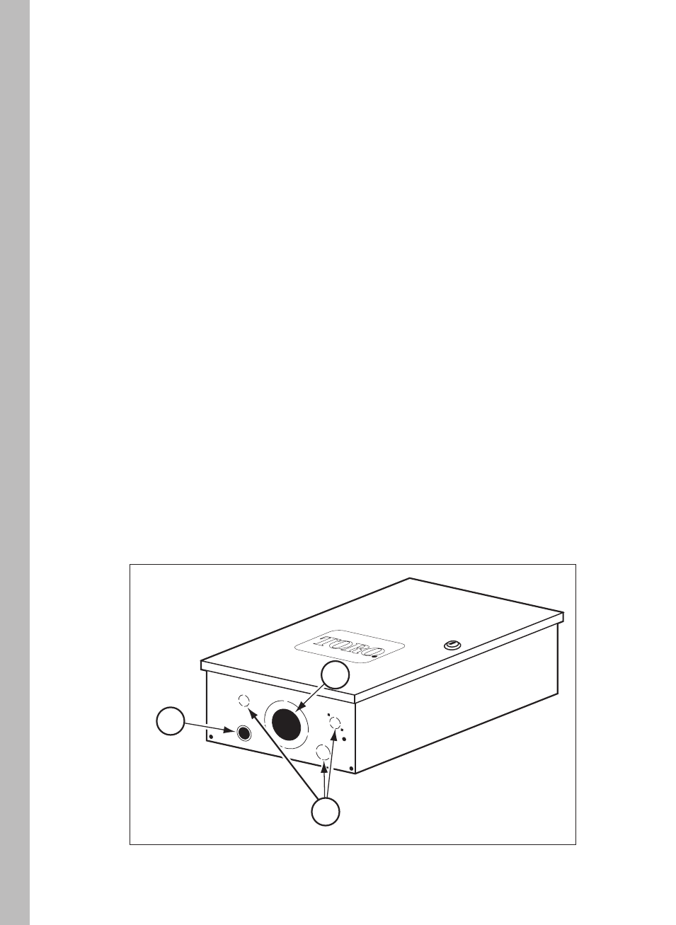
1. Remove terminal strip cover located below the transformer. Install
conduit from the circuit breaker panel to the controller cabinet using
the 1/2" (13 mm) thru-hole or 3/4" (19 mm) conduit knockout.
3. Auxiliary wiring conduit knockouts (use as preferred).
1
2
3
2. For field wiring, either 2" (51 mm) or 3" (75 mm) conduit can
be installed. For 3" (75 mm) conduit, remove the knockout ring
provided to increase the hole size. Sufficient space is provided
to enable either a hex nut or star nut to be installed on the
conduit fitting.