Toshiba RAS-B13GKVP-E User Manual
Page 97
– 97 –
No.
Part name
Electronic
expansion valve
coil
Procedure
1. Detachment
1) Perform step 1 in
, all the steps in
and 1 in
.
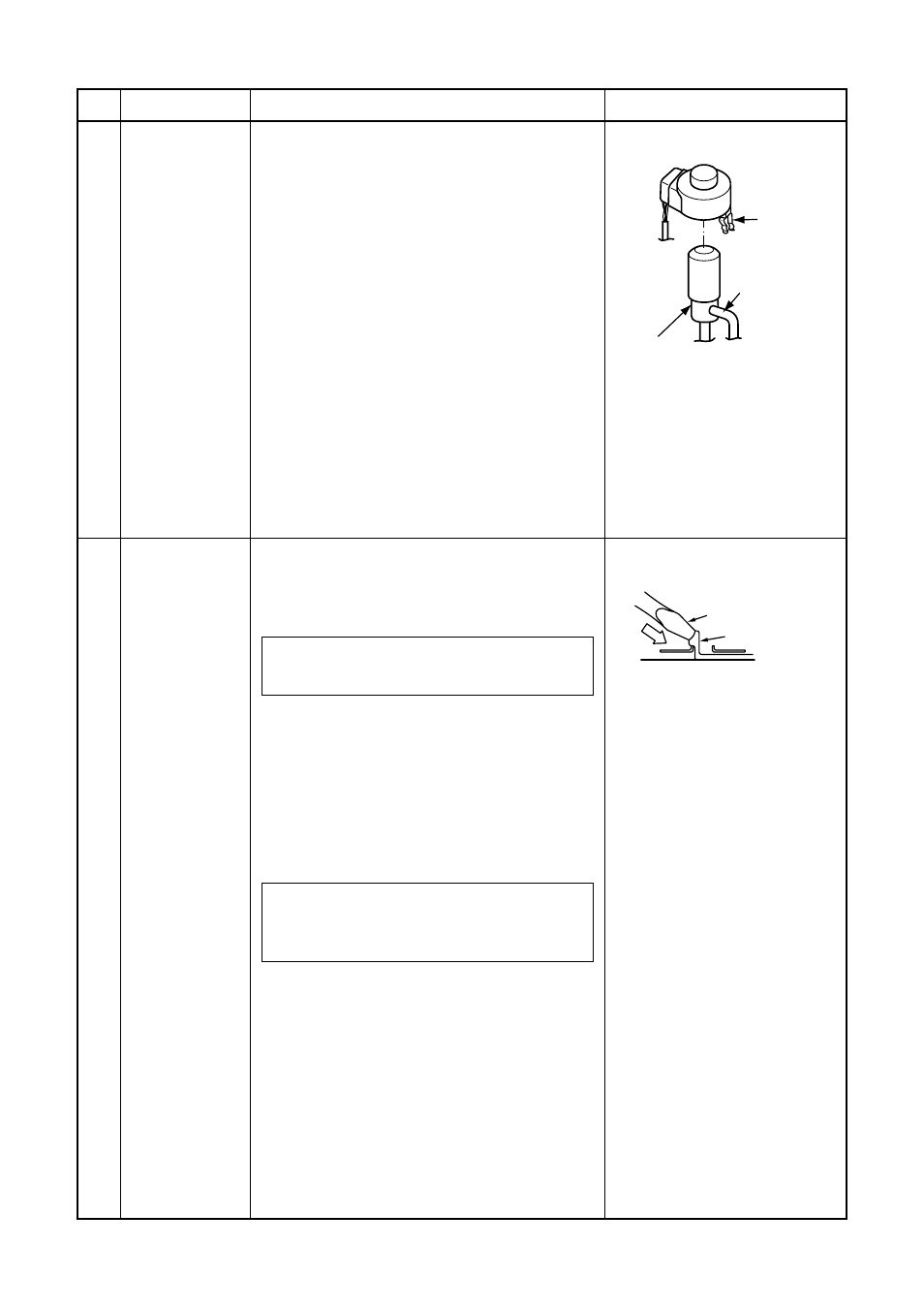
2) Remove the coil by pulling it up from the
electronic control valve body.
2. Attachment
1) When assembling the coil into the valve
body, ensure that the coil anti-turn lock is
installed properly in the pipe.
When handling the parts, do not pull the leads.
When removing the coil from the valve body, use
your hand to secure the body in order to prevent
the pipe from being bent out of shape.
Remarks
Hooking claw
Minus screwdriver
Coil inserting
position
Coil anti-turn
lock position
Coil
anti-turn
lock
Fan guard
1. Detachment
1) Perform work of item 1 of
.
2) Remove the front cabinet, and put it down
so that fan guard side directs downward.
Perform work on a corrugated cardboard,
cloth, etc. to prevent flaw to the product.
3) Remove the hooking claws by pushing minus
screwdriver according to the arrow mark in
the right figure, and remove the fan guard.
2. Attachment
1) Insert claws of the fan guard in the holes
of the front cabinet. Push the hooking
claws (9 positions) by hands and fix the
claws.
All the attaching works have completed.
Check that all the hooking claws are fixed
to the specified positions.