Toshiba RAS-B13GKVP-E User Manual
Page 92
– 92 –
No.
Part name
Front cabinet
Procedure
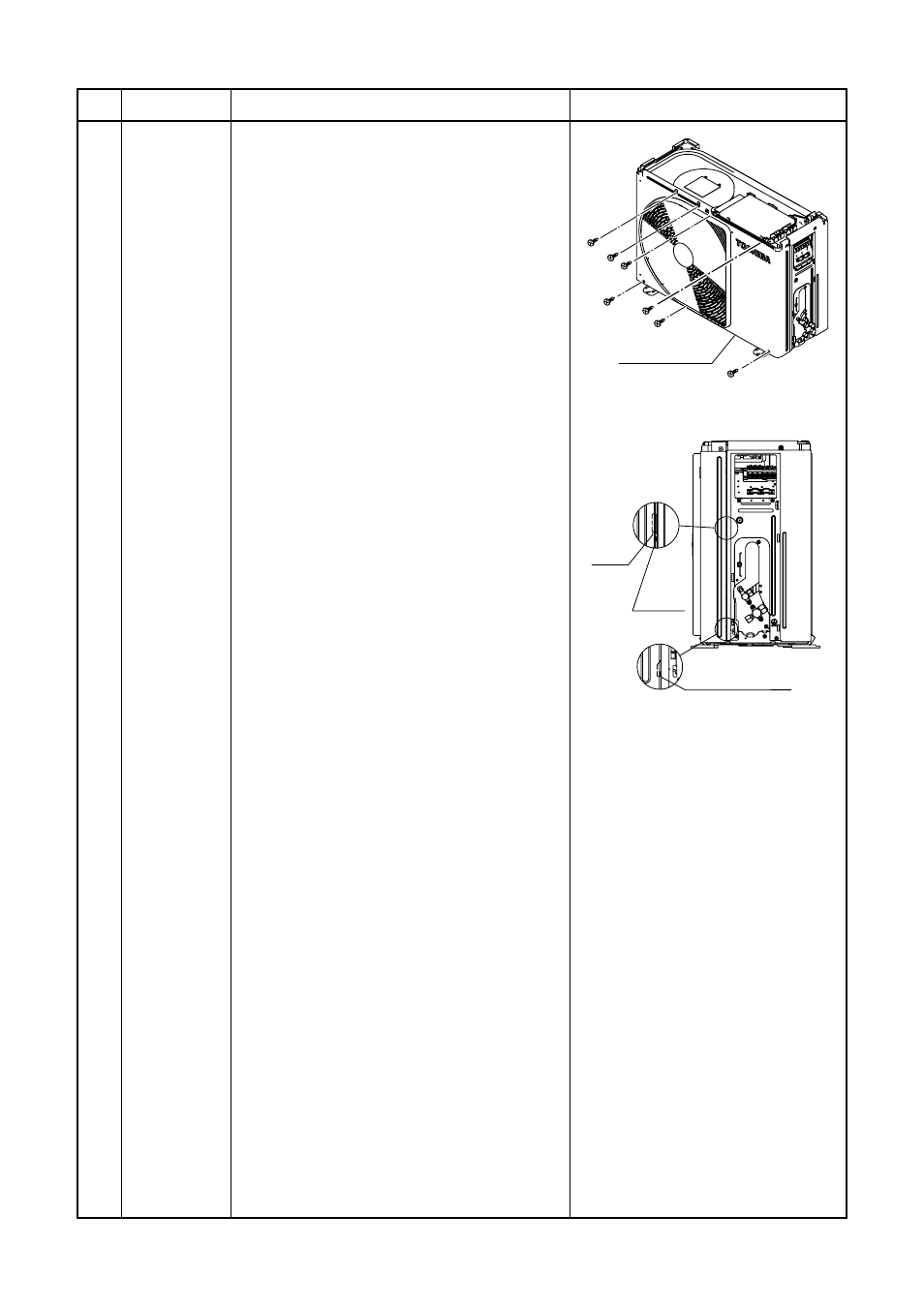
1. Detachment
1) Perform step 1 in
.
2) Remove the fixing screws (ST1TШ4 Ч 8L
2 pcs.) used to secure the front cabinet
and inverter cover, the screws (ST1TШ4
Ч 8L 3 pcs.) used to secure the front
cabinet at the bottom, and the fixing
screws (ST1TШ4 Ч 8L 2 pcs.) used to
secure the motor base.
• The front cabinet is fitted into the side
cabinet (left) at the front left side so
pull up the top of the front cabinet to
remove it.
2. Attachment
1) Insert the claw on the front left side into
the side cabinet (left).
2) Hook the bottom part of the front right
side onto the concave section of the
bottom plate. Insert the claw of the side
cabinet (right) into the square hole in the
front cabinet.
3) Return the screws that were removed
above to their original positions, and
attach them.the main unit, and attach it
pushing upward.
Remarks
Square
hole
Claw
Front cabinet
Concave section