Toshiba RAS-B13GKVP-E User Manual
Page 28
– 28 –
Item
2. Indoor fan
motor control
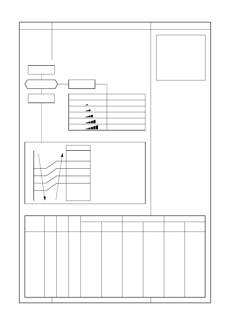
Operation flow and applicable data, etc.
(This operation controls the fan speed at indoor unit side.)
The indoor fan (cross flow fan) is operated by the phase-
control induction motor. The fan rotates in 5 stages in
MANUAL mode, and in 5 stages in AUTO mode, respec-
tively. (Table 1)
Description
* Symbols
UH
: Ultra High
H
: High
M+
: Medium+
M
: Medium
L+
: Low+
L
: Low
L-
: Low–
UL
: Ultra Low
SUL
: Super Ultra Low
* The fan speed broadly varies due
to position of the louver, etc.
The described value indicates one
under condition of inclining
downward blowing.
1) When setting the fan speed to L,
L+, M, M+ or H on the remote
controller, the operation is
performed with the constant
speed shown in Fig. 1.
2) When setting the fan speed to
AUTO on the remote controller,
revolution of the fan motor is
controlled to the fan speed level
shown in Fig. 2 and Table 1
according to the setup tempera-
ture, room temperature, and heat
exchanger temperature.
(Fig. 1)
(Fig. 2)
(Table 1) Indoor fan air flow rate
Fan speed
level
WF
WE
WD
WC
WB
WA
W9
W8
W7
W6
W5
W4
W3
W2
W1
COOL
UH
H
M+
M
L+
L
L–
UL
SUL
HEAT
UH
H
M+
M
L+
L
L–
UL
SUL
DRY
L+
L
L–
UL
SUL
RAS-B10GKVP-E
Fan speed
Air flow rate
(rpm)
(m
3
/h)
1630
684
1480
609
1400
569
1350
544
1200
468
1110
423
980
358
910
323
900
318
890
313
880
308
730
232
580
157
430
82
400
67
RAS-B13GKVP-E
Fan speed
Air flow rate
(rpm)
(m
3
/h)
1650
694
1530
634
1440
589
1390
564
1240
488
1150
443
1010
373
910
323
900
318
890
313
880
308
730
232
580
157
430
82
400
67
RAS-B16GKVP-E
Fan speed
Air flow rate
(rpm)
(m
3
/h)
1650
694
1580
659
1550
644
1530
634
1380
559
1230
483
1080
408
970
353
960
348
950
343
940
338
790
263
640
187
490
112
400
67
+2.5
Ta
[˚C]
+2.0
+1.5
+1.0
+0.5
Tsc
a
b
c
d
e
M+(WB)
*3
*4
*5
L(W6)
Air volume AUTO
L
L+
M
M+
H
W6
(L + M) / 2
W9
(M + H) / 2
WC
Indication
Fan speed
Fan speed setup
COOL ON
AUTO
MANUAL
*3 : Fan speed = (M + –L) x 3/4 + L
*4 : Fan speed = (M + –L) x 2/4 + L
*5 : Fan speed = (M + –L) x 1/4 + L
(Linear approximation
from M+ and L)