Toshiba RAS-B13GKVP-E User Manual
Page 85
– 85 –
No.
Part name
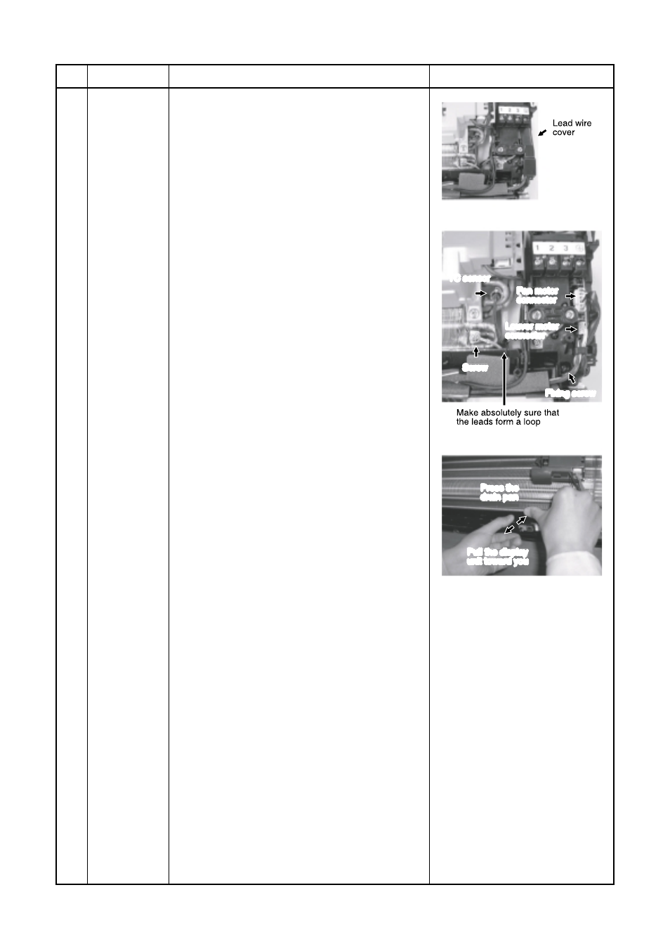
Electric parts
box assembly
Procedures
1) Follow the procedure up to 4) in
above.
2) Remove screw of earth lead attached to the
end plate of the evaporator.
3) Remove the lead wire cover, and remove
connector (5P) for the fan motor and connec-
tor (5P) for the louver motor from the electric
parts box assembly.
4) Pull out TC sensor from sensor holder of the
evaporator.
Remarks
Fixing screw
TC sensor
Louver moter
connector
Fan motor
connector
Screw
Press the
drain pan
Pull the display
unit toward you
5) Disengage the two claws at the top of the
display unit.
(They can be easily disengaged by pressing
the drain pan above the claws and at the
same time pulling the display unit toward you.)
6) Remove the fixing screw that secures the
electric parts box assembly, and remove the
assembly.
1) Hook the top part of the electric parts box
assembly onto the claws on the back body,
and secure it using the fixing screw.
Now attach the display unit. Connect the
connectors for the fan motor and louver motor.
2) Secure the grounding wire using the fixing
screw. Insert the TC sensor into the sensor
holder.
* Be absolutely sure to loop the grounding
wire and TC sensor leads once at the
bottom.