3 device tab – Renesas Single-Chip Microcomputer M306NKT3 User Manual
Page 106
90
FDM\E8Direct Pins
This section displays the direction and state of the controlled mode pins for the Connect and
Disconnect with Reset operations.
8.5.3
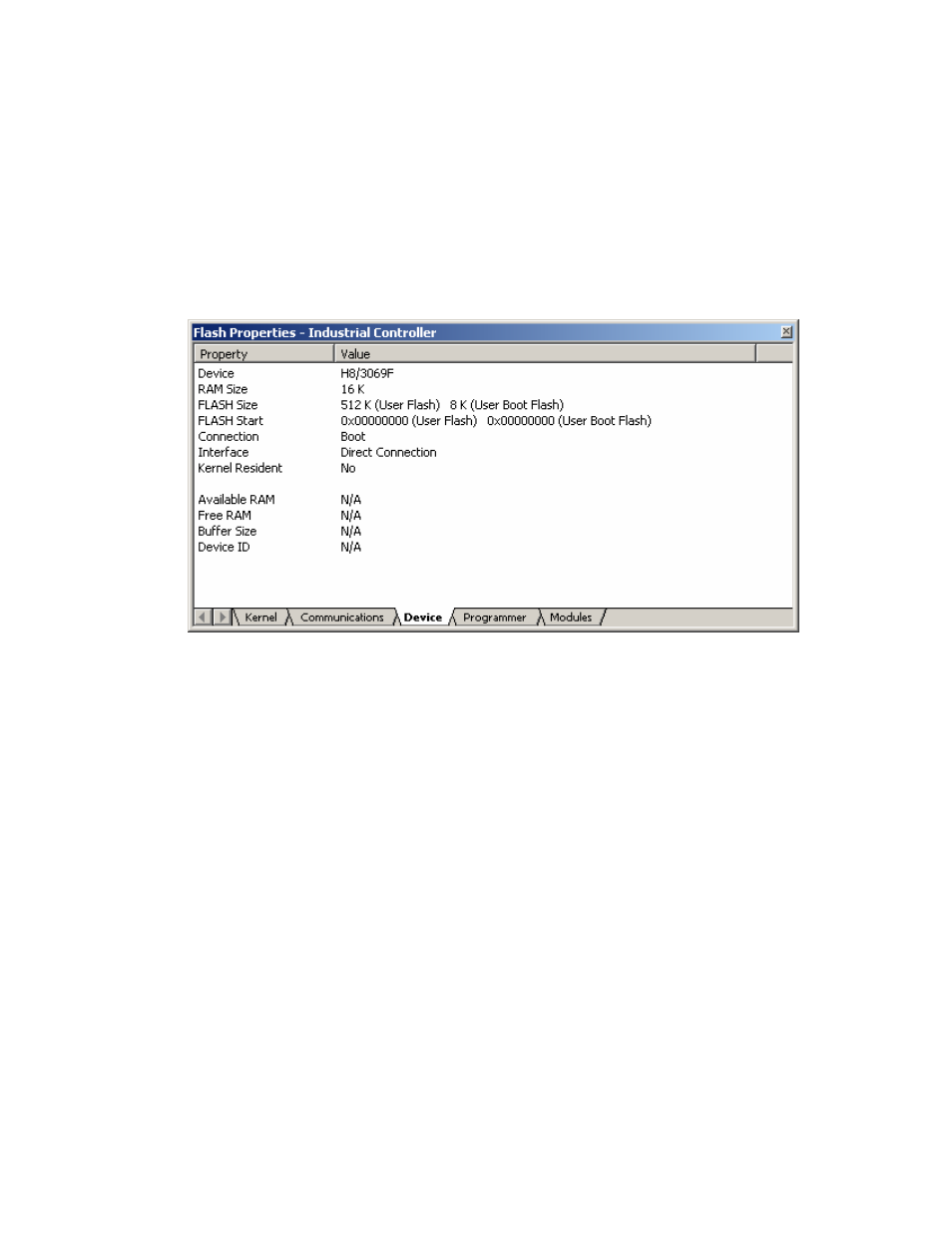
Device Tab
This shows the device information. It also allows the user to select BOOT Mode or USER Program
Mode and the ‘Direct Connection’ interface. In addition, it can specify whether or not the kernel is in
the target device.
Figure 8-10 Device Properties
Device
Displays the name of the active device. Double clicking invokes the Project Wizard to allow
editing of this item.
RAM Size, FLASH Size, Flash Start
These are for display only and are not editable.
Connection
Boot Mode: This connection type specifies that the on-board programming BOOT mode
sequence is to be initiated. This will cause the entire FLASH memory to be erased and a kernel
loaded.
USER (Program) Mode: This connection type specifies that the on-board programming USER
Program mode sequence is to be initiated by a previously loaded user program that is used to
reprogram the FLASH memory.