Normal mode – parallel, 2 normal mode – parallel – Powerware 9390 UPS 100160 kVA User Manual
Page 61
UNDERSTANDING UPS OPERATION
EATON Powerware
®
9390 UPS (20–80 kVA) Installation and Operation Manual
S 164201603 Rev 2 www.powerware.com
7-9
7.2.2
Normal Mode – Parallel
In Normal mode, utility AC power is supplied to the UPMs. Each UPM then conditions
the incoming AC power and provides clean, regulated AC power to either a module
tie cabinet or distribution panel for parallel systems up to four modules. The applied
load is equally shared among the available UPMs in the system.
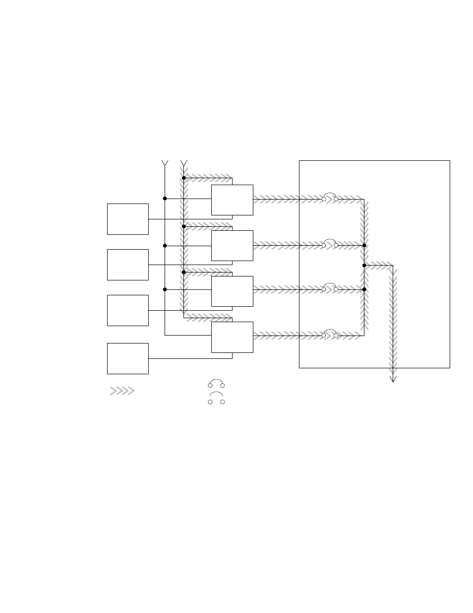
Figure 7‐5 shows the path of electrical power through the parallel system when
operating in Normal mode.
Main Power Flow
UPM 1
UPM 2
UPM 3
UPM 4
Output to
Critical
Load
Battery
UPM Input
Module Tie Cabinet
UPM 1 Output
Bypass Input
UPM 2 Output
UPM 3 Output
UPM 4 Output
Battery
Battery
Battery
Closed
Open
Breakers
Figure 7‐5. Path of Current through the UPMs in Normal Mode – Parallel
If the utility AC power is interrupted or is out of specification, the UPMs automatically
switch to Battery mode to support the critical load without interruption. When utility
power returns, the UPMs return to Normal mode.
If the UPMs become overloaded or unavailable, the parallel system switches to
Bypass mode. The parallel system automatically returns to Normal mode when the
overload condition is cleared and system operation is restored within specified limits.