Through table j, Able j for neutral bonding jumper wire sizes – Powerware 9390 UPS 100160 kVA User Manual
Page 163
POWER WIRING INSTALLATION NOTES
071608
D
5 of 23
DESCRIPTION:
DATE:
DRAWING NO:
SHEET:
REVISION:
INSTALLATION INFORMATION
EATON Powerware
®
9390 UPS (20–80 kVA) Installation and Operation Manual
S 164201603 Rev 2 www.powerware.com
A-15
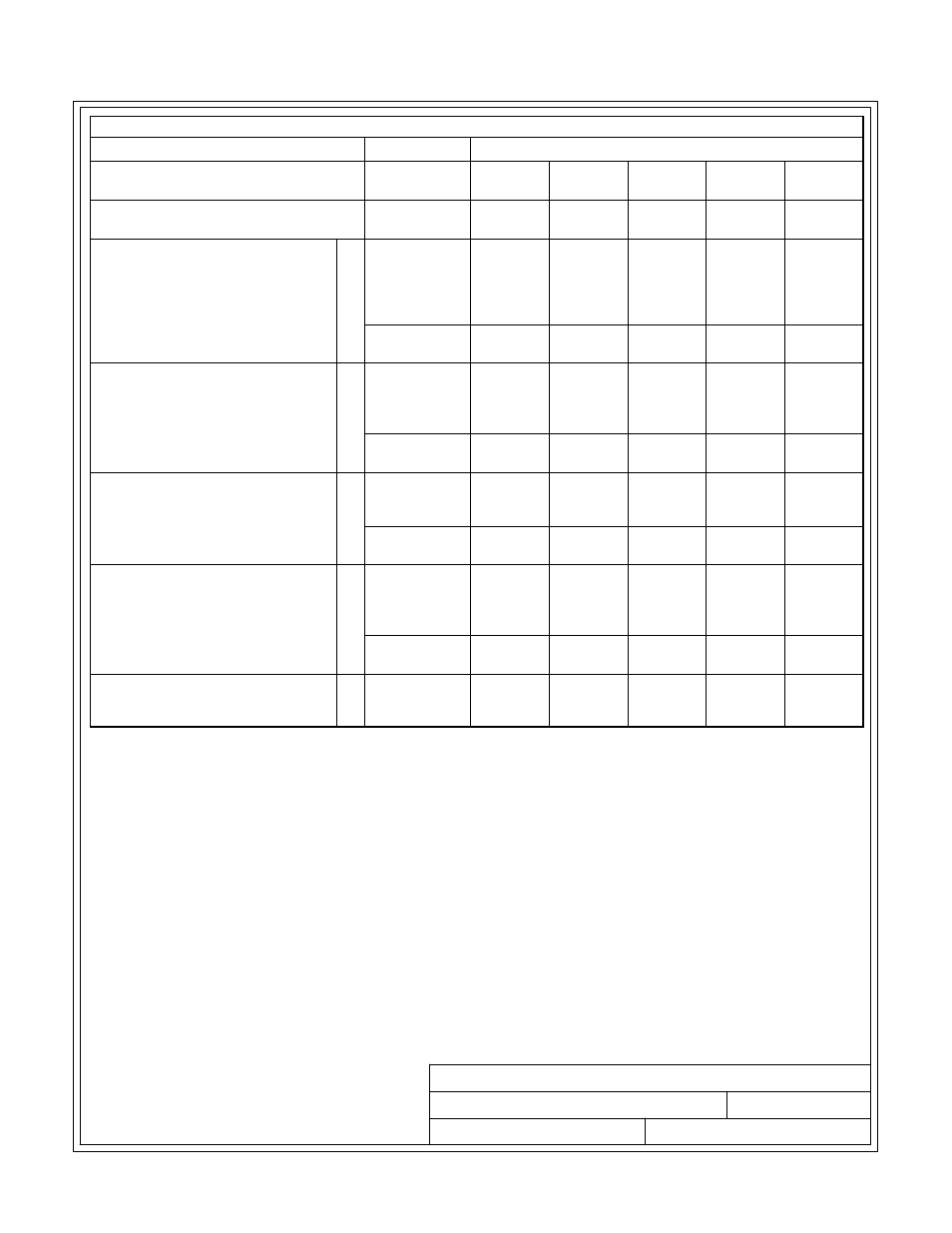
Table I. INPUT/OUTPUT Ratings & External Wiring Requirements for the Powerware 9390-80/60
Units
Rating 50/60 Hz
Basic Unit Rating at 0.9 lagging pF load
kVA
kW
60
54
60
54
60
54
60
54
60
54
Input and Bypass Input
Output
VOLTS
VOLTS
208/220
208/220
380
380
400
400
415
415
480
480
AC Input to UPS Rectifier
(0.98 min. pF)
Full Load Current plus Battery
Recharge Current
(3) Phases, (1) Ground
A
Amps
185
100
98
95
80
Minimum Conductor Size
Number per Phase
AWG or kcmil
(each)
250
(1)
1/0
(1)
1/0
(1)
1/0
(1)
1
(1)
AC Input to UPS Bypass
Full Load Current
(3) Phases, (1) Neutral-if required,
(1) Ground
B
Amps
167/158
91
87
84
72
Minimum Conductor Size
Number per Phase
AWG or kcmil
(each)
250
(1)
1/0
(1)
1/0
(1)
1/0
(1)
1
(1)
DC Input from Battery to UPS
(1) Positive, (1) Negative
C
Vdc
Amps@
(2.0V/cell)
384-480
151
432-480
151
432-480
151
432-480
151
432-480
151
Minimum Conductor Size
Number per Pole
AWG or kcmil
(each)
2/0
(1)
2/0
(1)
2/0
(1)
2/0
(1)
2/0
(1)
AC Output to Critical Load
Full Load Current
(3) Phases, (1) Neutral-if required, (1)
Ground
D
Amps
167/158
91
87
84
72
Minimum Conductor Size
Number per Phase
AWG or kcmil
(each)
250
(1)
1/0
(1)
1/0
(1)
1/0
(1)
1
(1)
Neutral Bonding Jumper
Minimum Conductor Size
Number (See Note 7)
-
AWG or kcmil
(each)
2
(1)
6
(1)
6
(1)
6
(1)
6
(1)
NOTE Callout letters
A
,
B
,
C
, and
D