Through table v – Powerware 9390 UPS 100160 kVA User Manual
Page 179
POWER WIRING INSTALLATION NOTES
071608
D
21 of 23
DESCRIPTION:
DATE:
DRAWING NO:
SHEET:
REVISION:
INSTALLATION INFORMATION
EATON Powerware
®
9390 UPS (20–80 kVA) Installation and Operation Manual
S 164201603 Rev 2 www.powerware.com
A-31
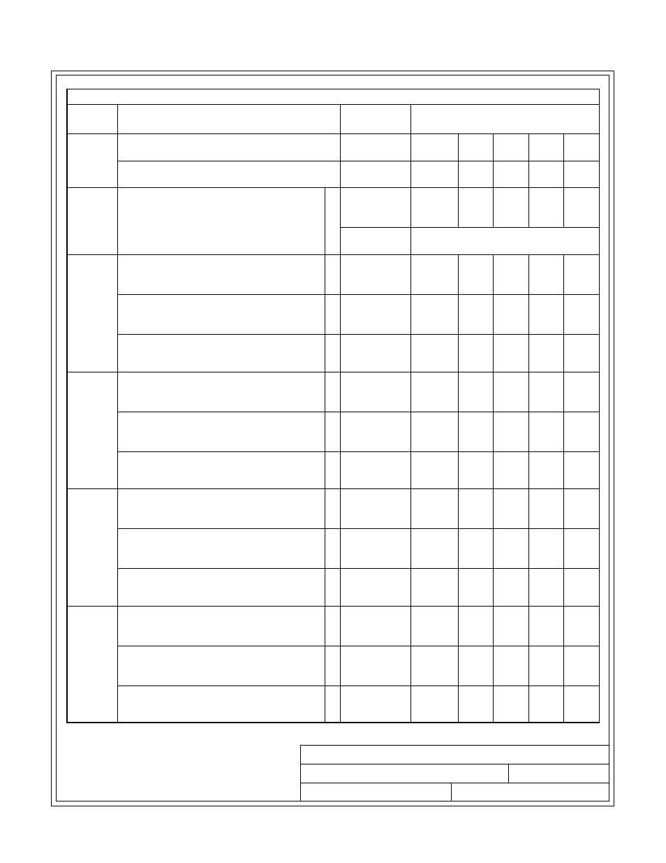
Table U. INPUT/OUTPUT Ratings for Powerware 9390-80/60 Parallel System
Configu
ration
Units
Rating 50/60 Hz
Basic Unit Rating at 0.9 lagging pF load
kVA
kW
60
54
60
54
60
54
60
54
60
54
Input and Bypass Input
Output
VOLTS
VOLTS
208/220
208/220
380
380
400
400
415
415
480
480
All
AC Input from UPM
Full Load Current for each Module
(3) Phases, (1) Neutral, (1) Ground
D
Amps
167/158
92
87
84
73
Minimum Conductor Size for each Module
Number per Phase for each Module
AWG or kcmil
(each)
See Table G through Table J for wire
size.
1+1
AC Input to Tie Cabinet Bypass (optional)
Full Load Current
(3) Phases, (1) Neutral-if required, (1) Ground
F
Amps
167/158
92
87
84
73
AC Output to Critical Load
Full Load Current
(3) Phases, (1) Neutral, (1) Ground
G
Amps
167/158
92
87
84
73
System Neutral Bonding Jumper
Minimum Conductor Size
Number (See Note 28)
-
AWG or kcmil
(each)
2
(1)
6
(1)
6
(1)
6
(1)
6
(1)
2+0
and
2+1
AC Input to Tie Cabinet Bypass (optional)
Full Load Current
(3) Phases, (1) Neutral-if required, (1) Ground
F
Amps
334/316
184
174
168
146
AC Output to Critical Load
Full Load Current
(3) Phases, (1) Neutral, (1) Ground
G
Amps
334/316
184
174
168
146
System Neutral Bonding Jumper
Minimum Conductor Size
Number (See Note 28)
-
AWG or kcmil
(each)
1/0
(1)
4
(1)
4
(1)
4
(1)
4
(1)
3+0
and
3+1
AC Input to Tie Cabinet Bypass (optional)
Full Load Current
(3) Phases, (1) Neutral-if required, (1) Ground
F
Amps
501/474
276
261
252
219
AC Output to Critical Load
Full Load Current
(3) Phases, (1) Neutral, (1) Ground
G
Amps
501/474
276
261
252
219
System Neutral Bonding Jumper
Minimum Conductor Size
Number (See Note 28)
-
AWG or kcmil
(each)
2/0
(1)
1/0
(1)
1/0
(1)
1/0
(1)
2
(1)
4+0
AC Input to Tie Cabinet Bypass (optional)
Full Load Current
(3) Phases, (1) Neutral-if required, (1) Ground
F
Amps
668/632
368
348
336
292
AC Output to Critical Load
Full Load Current
(3) Phases, (1) Neutral, (1) Ground
G
Amps
668/632
368
348
336
292
System Neutral Bonding Jumper
Minimum Conductor Size
Number
(See Note 28)
-
AWG or kcmil
(each)
3/0
(1)
1/0
(1)
1/0
(1)
1/0
(1)
1/0
(1)
NOTE Callout letters
D
,
F
, and
G