Powerware 9390 UPS 100160 kVA User Manual
Page 181
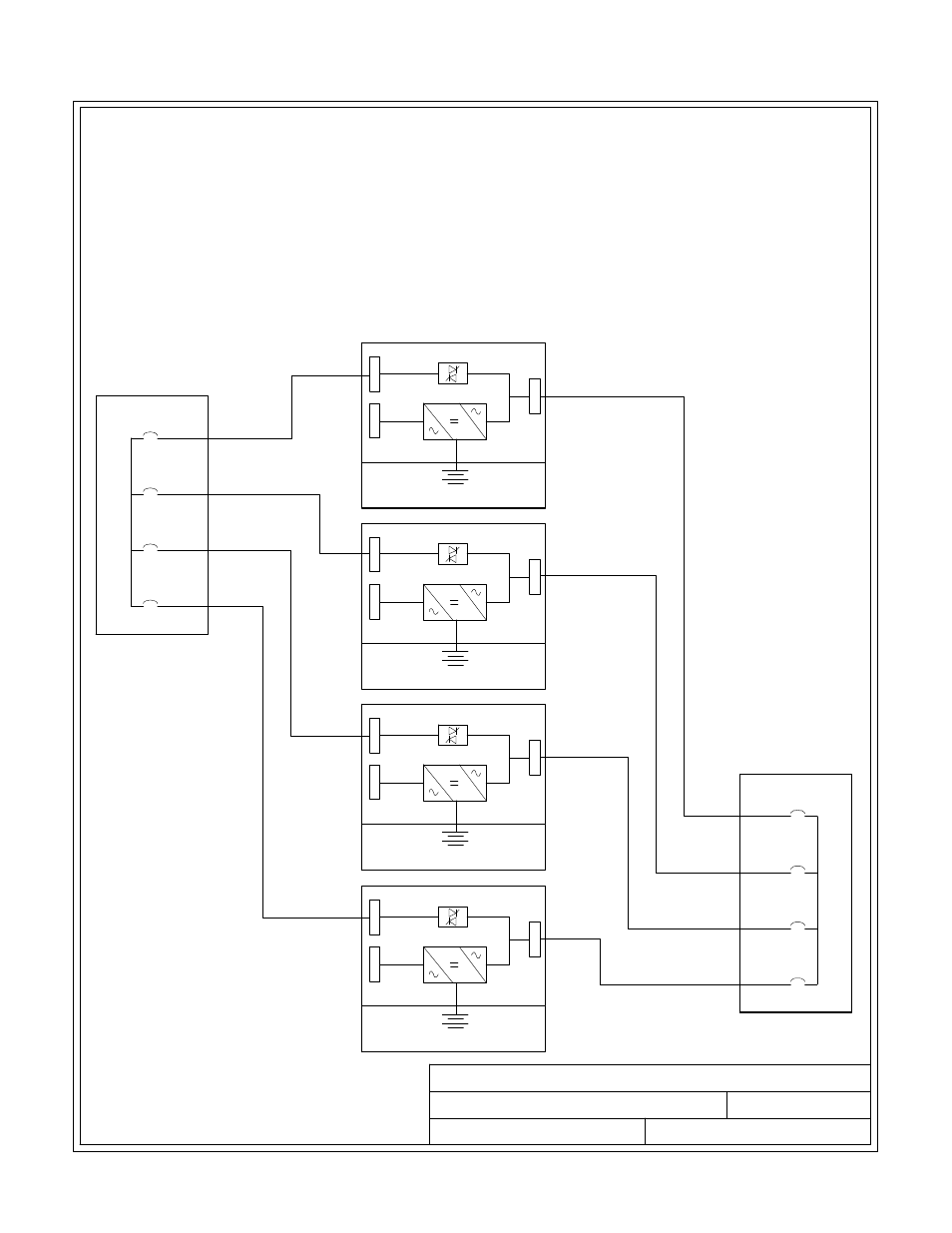
POWER WIRING INSTALLATION NOTES
110106
B
DESCRIPTION:
DATE:
DRAWING NO:
SHEET:
REVISION:
UPM 2
Battery
Bypass inputs to UPMs
UPM 1
Battery
UPM 3
Battery
UPM 4
Battery
Outputs from UPMs
1A
2A
3A
4A
1B
2B
3B
4B
23 of 23
INSTALLATION INFORMATION
EATON Powerware
®
9390 UPS (20–80 kVA) Installation and Operation Manual
S 164201603 Rev 2 www.powerware.com
A-33
33.
Required parallel system wiring length should be in accordance with the following rule, as
referenced to the diagram below, to ensure approximately equal current sharing when in
Static Bypass mode:
(Total length of 1A + 1B)
(Total length of 2A + 2B) (Total length of 3A + 3B) (Total length of 4A + 4B)
This rule has a tolerance of approximately
10% for the combined input and output wire
lengths.
If installing only two UPMs in a fully redundant system, this requirement is no longer
required, as each UPM is capable of supporting the full bypass requirement. However, this
would preclude future expansion.