Powerware 9390 UPS 100160 kVA User Manual
Page 194
032406
B
DESCRIPTION:
DATE:
DRAWING NO:
SHEET:
REVISION:
INTERFACE WIRING INSTALLATION
NOTES AND TERMINAL LOCATIONS
5 of 15
INSTALLATION INFORMATION
EATON Powerware
®
9390 UPS (20–80 kVA) Installation and Operation Manual
S 164201603 Rev 2 www.powerware.com
A-46
9.
The UPS DC UVR trip and Battery Aux signal wiring from the UPS must be connected to
the DC source disconnect device.
10.
Battery Aux and UVR wiring should be a minimum of 18 AWG.
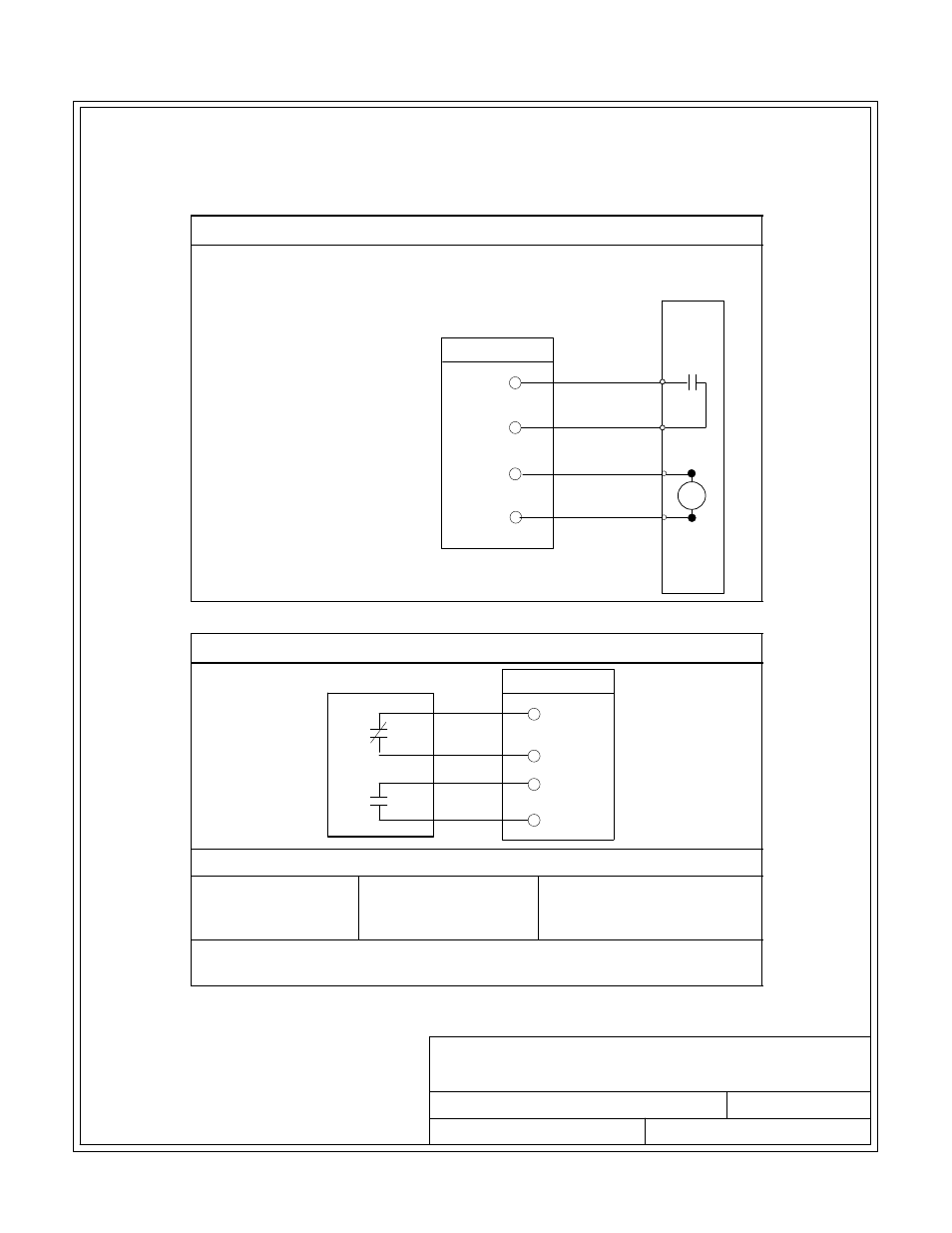
Table X. Battery Disconnect Interface
BATTERY AUX +
BATTERY
BREAKER OR
DISCONNECT
6
7
8
TB1
5
BATTERY AUX -
BATTERY UVR +
BATTERY UVR -
UPS
Table Y. Alarm Relay Contact
7
5
6
ALARM RELAY
TB2
8
UPS
CONTACT RATING
Switched Voltage:
277 Vac
28 Vdc
Maximum Current: 5A
Minimum Wire Size: 22 AWG
NOTE:
Relays are shown in de‐energized state. Relays change state when the
UPS is in Normal mode.