Through table m – Powerware 9390 UPS 100160 kVA User Manual
Page 166
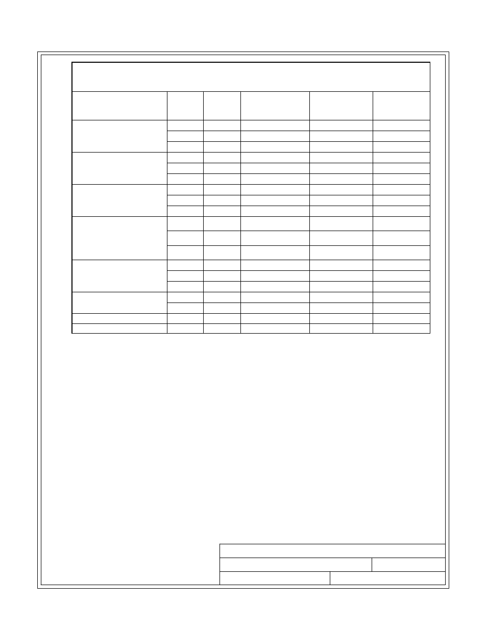
POWER WIRING INSTALLATION NOTES
071608
C
NOTE Customer ground can be run in any conduit listed in Table N.
8 of 23
DESCRIPTION:
DATE:
DRAWING NO:
SHEET:
REVISION:
INSTALLATION INFORMATION
EATON Powerware
®
9390 UPS (20–80 kVA) Installation and Operation Manual
S 164201603 Rev 2 www.powerware.com
A-18
Table L. UPS Cabinet Power Cable Terminations for the Powerware 9390-40/20,
9390-40/30, and 9390-40/40 (208V/220V Input and 208V/220V Output and
380V/400V/415V/480V Input and 380V/400V/415V/480V Output)
Terminal Function
Terminal Function
Size of Pressure
Termination
Tightening
Torque
Nm (lb in)
Type
Screw
AC Input to UPS Rectifier
and Bypass
(Single Input)
E6
Phase A
1 - #14-2/0
13.5 (120)
3/16 in. Hex
E7
Phase B
1 - #14-2/0
13.5 (120)
3/16 in. Hex
E8
Phase C
1 - #14-2/0
13.5 (120)
3/16 in. Hex
AC Input to UPS Rectifier
(Dual Input)
E1
Phase A
1 - #14-2/0
13.5 (120)
3/16 in. Hex
E2
Phase B
1 - #14-2/0
13.5 (120)
3/16 in. Hex
E3
Phase C
1 - #14-2/0
13.5 (120)
3/16 in. Hex
AC Input To Bypass
(Dual Input)
E6
Phase A
1 - #14-2/0
13.5 (120)
3/16 in. Hex
E7
Phase B
1 - #14-2/0
13.5 (120)
3/16 in. Hex
E8
Phase C
1 - #14-2/0
13.5 (120)
3/16 in. Hex
Single‐Feed To Dual‐Feed
Remove Jumpers between
Rectifier Input Terminals
and Bypass Input
Terminals
—
Phase A
N/A
5.6 (50)
1/4–20 Hex Nut
—
Phase B
N/A
5.6 (50)
1/4–20 Hex Nut
—
Phase C
N/A
5.6 (50)
1/4–20 Hex Nut
AC Output to
Critical Load
E9
Phase A
1 - #14-2/0
13.5 (120)
3/16 in. Hex
E10
Phase B
1 - #14-2/0
13.5 (120)
3/16 in. Hex
E11
Phase C
1 - #14-2/0
13.5 (120)
3/16 in. Hex
DC Input from
Battery to UPS
E4
Positive
1 - #14-2/0
13.5 (120)
3/16 in. Hex
E5
Negative
1 - #14-2/0
13.5 (120)
3/16 in. Hex
Input and Output Neutral
E12
Neutral
4 - #14-1/0
5.6 (50)
Slotted
Customer Ground
Ground
Ground
8 - #14-1/0
5.6 (50)
Slotted