Powerware hot sync can bridge card – Powerware 9390 UPS 100160 kVA User Manual
Page 198
091505
A
DESCRIPTION:
DATE:
DRAWING NO:
SHEET:
REVISION:
INTERFACE WIRING INSTALLATION
NOTES AND TERMINAL LOCATIONS
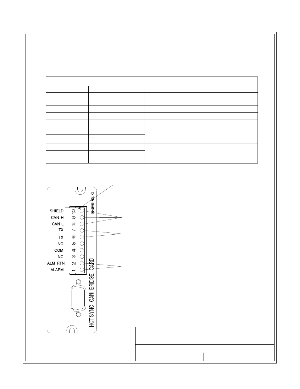
POWERWARE HOT SYNC CAN BRIDGE CARD
CONNECTIONS FOR PARALLEL SYSTEM CONTROL
CONNECTIONS FOR RMP, RIM, OR SCM
(ONLY ONE DEVICE CAN BE CONNECTED AT A TIME)
BUILDING ALARM 2 REPLACEMENT
J3
NOTE
All interface wiring is to be
provided by the customer.
9 of 15
INSTALLATION INFORMATION
EATON Powerware
®
9390 UPS (20–80 kVA) Installation and Operation Manual
S 164201603 Rev 2 www.powerware.com
A-50
16.
Conduit must be installed between the UPM cabinets for parallel interface wiring. Install the
interface wiring in separate conduit from the power wiring.
17.
Use Class 1 wiring methods (as defined by the NEC) for parallel interface wiring. The wire
should be shielded twisted pair, rated for 5 amps maximum.
18.
See Table AC and Chapter 6 for parallel interface wiring.
Table AC. Powerware Hot Sync
®
CAN Bridge Card Interface Connections
Terminal J3
Name
Description
1
Alarm
Programmable UPS alarm. Activated by a remote
dry contact closure.
2
Alarm Rtn
3
Not Used
Not Used
4
Not Used
Not Used
5
Not Used
Not Used
6
TX
Remote Monitor Panel (RMP), Relay Interface
Module (RIM), or Supervisory Contact Module
(SCM) connections.
7
TX
8
CAN L
Computer Area Network (CAN) Input for parallel
operation.
9
CAN H
10
Shield