37 dab1 distributed audio system, Ir learner , on page 39 – Sonance DAB1 User Manual
Page 37
37
DAB1 DISTRIBUTED AUDIO SYSTEM
NOTE: If the desired remote is not in the library,
try using a similar product remote from that man-
ufacturer. If that doesn’t work, see Adding IR
Codes to the User IR Library with the OptiLinQ
®
IR Learner, on page 39.
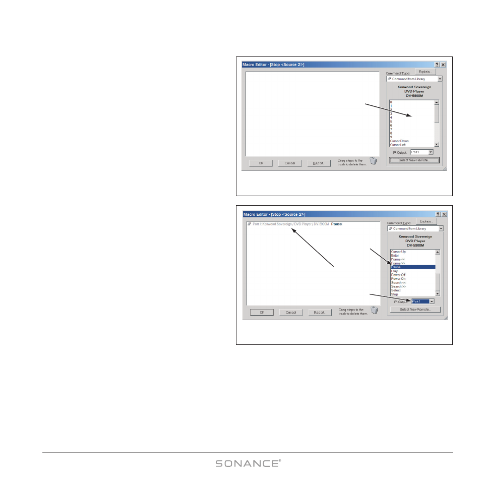
5. Select the device. Its commands will appear in the
small IR C
OMMAND
W
INDOW
on the M
ACRO
E
DITOR
Screen (see
Figure 47).
6. Select the desired command in the list and drag it to
the screen’s large M
ACRO
window. (In this example,
the P
AUSE
command — see
Figure 48).
7. Click OK. The M
ACRO
E
DITOR
screen will disappear.
There should now be a M
ACRO
I
NDICATOR
on the
Source 2 S
TOP
button on the P
RESS
level.
8. Select the P
RESS
-
AND
-H
OLD
button action level. The
M
ACRO
I
NDICATOR
should disappear from the Source
2 S
TOP
button.
9. Right-click on the Source 2 S
TOP
button.
10. Select the S
TOP
command from the IR Command
Window and drag it into the M
ACRO
W
INDOW
.
11. Click OK. M
ACRO
E
DITOR
screen will disappear.
There should now be a M
ACRO
I
NDICATOR
on the
Source 2 S
TOP
button on the P
RESS
-A
ND
-H
OLD
level.
P
ROGRAMMED
IR O
UTPUT
P
ORT
S
ELECTOR
The default P
ROGRAMMED
IR Port settings match the four
input sources: Programmed IR Port 1 = Source 1, etc.
You can use the P
ROGRAMMED
IR O
UTPUT
P
ORT
S
ELECTOR
to
route the commands to other ports by selecting the
desired port
before you drag the command into the
M
ACRO
W
INDOW
.
In a system that has duplicate same-make/same-model source components, routing macro IR commands out of the C
OMMON
IR outputs will cause both of those components to respond to all macro commands for that component. If you want to retain
individual control of the components in macros you will need to connect IR emitters to two P
ROGRAMMED
IR outputs and
create separate macro commands for each component, with those commands routed to individual P
ROGRAMMED
IR outputs
for each component.
For example, in a system with duplicate CD changers connected to the DAB1’s S
OURCE
3 and S
OURCE
4 inputs, connect the IR
emitter for the S
OURCE
3 CD player to P
ROGRAMMED
IR O
UTPUT
#3 and the IR emitter for the S
OURCE
4 CD player to P
ROGRAMMED
IR O
UTPUT
#4. Make sure that all of the IR macro commands for the S
OURCE
3 CD player are routed to P
ROGRAMMED
IR P
ORT
Select
IR Command
Programmed
IR Output Port
Selector
Drag Command
into Macro Window
Figure 48:
Dragging Commands into the M
ACRO
W
INDOW
IR Command
Window
Figure 47:
M
ACRO
E
DITOR
Screen with IR C
OMMAND
L
IBRARY
Selected