16 dab1 distributed audio system, Control output, control input and sync connections – Sonance DAB1 User Manual
Page 16
16
DAB1 DISTRIBUTED AUDIO SYSTEM
5
5.. C
C
O
O M
M M
M O
O N
N
IIRR O
O
U
U TT
PPoorrttss:: Four 3.5mm mini jacks that output all IR commands regardless of zone for all source compo-
nents (all zones have control of all sources). Intended for all systems except those that contain multiple same-brand,
same-model source components.
• Connect one Sonance OptiLinQ-type IR emitter to each C
OMMON
IR Out port for each common source component
to be controlled. Attach one emitter to the IR window on each source component.
6
6.. LL
O
O C
C A
A LL
IIRR O
O
U
U TT
PPoorrttss:: Six 3.5mm mini jacks (one for each zone) that allow control of a specific source component from
a specific zone. Connect one Sonance OptiLinQ-type emitter to the appropriate L
OCAL
IR O
UT
jack and attach the
emitter to the source component’s IR window.
EExxaam
mppllee:: The living room is Zone 1. The CD changer is Source 2 and is to be controlled
only from the living room.
Connect the IR emitter to the Zone 1 L
OCAL
IR O
UT
jack and attach it to the IR window on the CD changer.
The CD changer can be controlled only from the living room, but all zones can still select Source 2 and listen to the CD
changer when it is playing.
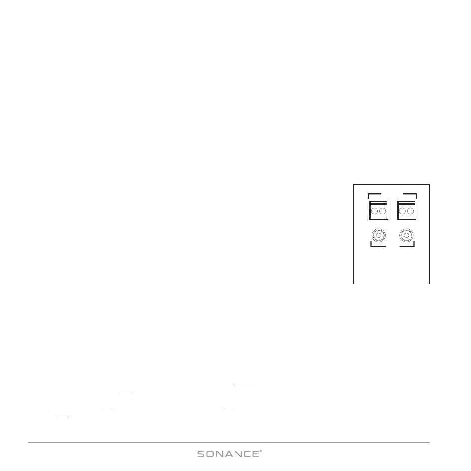
Control Output, Control Input and Sync Connections
(see Figure 12)
C
O N T R O L
O
U T
T e r m i n a l
One 2-wire screw connector that outputs 12VDC @ 100mA when at least one DAB1 zone is
active. Turns OFF (0VDC) when all zones are OFF. Can be used for triggering external devices
such as a zone-specific external amplifier. Accepts one pair 14 – 24 AWG wire.
C
O N T R O L
I
N P U T
T e r m i n a l
A general trigger input that can be used for Paging or sense input as part of a DAB1 S
TATUS
test in a macro. Requires 5 – 24V AC or DC @ 100mA. Accepts one pair 14 – 24AWG wire.
W i r i n g t h e C
O N T R O L
C o n n e c t i o n s
1. Strip approximately ¼" of insulation from each conductor and twist the strands until tight
to prevent stray strands.
2. Be sure to maintain proper polarity by connecting the appropriate ‘+V’ and ‘GND’ terminals on the device to the
appropriate ‘+V’ and ‘GND’ terminals on the DAB1. Be sure the connections are tight and that there are no frayed ends
sticking out that could cause a short-circuit.
S
Y N C
C o n n e c t i o n s
Two 3.5mm mini jacks that are used to trigger-link up to four DAB1s to provide communication between multiple DAB1
units that form large systems with more than 6 zones. For details, see
Appendix 1: Party Mode , on page 54. Use mono
3.5mm mini cables to daisy-chain the S
YNC
jacks of all DAB1 units in the system.
Audio and IR will pass-through multiple DAB1s that are in the Standby mode. Power for the source components should be
managed separately or left ON.
If no other zones are ON and a zone on a DAB1 is turned ON with a Source button P
RESS
, only that DAB1 and that zone
will turn ON.
+ OUT -
INPUT
12 VDC @
100 mA
+6 -24
AC/DC
CONTROL
SYNC
Figure 12:
Control Input/ Output
and Sync Connections