Sonance DAB1 User Manual
Page 13
13
DAB1 DISTRIBUTED AUDIO SYSTEM
W i r i n g t h e S p e a k e r C o n n e c t o r s
The DAB1’s speaker outputs are rated for 8-ohm nominal speakers.
1. Run speaker wire from each speaker to the controller location. We recommend that you
mark each wire’s positive (‘+’) and negative (‘–’) leads, its channel (left or right) and
which zone it is from so that you can connect it to the proper speaker terminals.
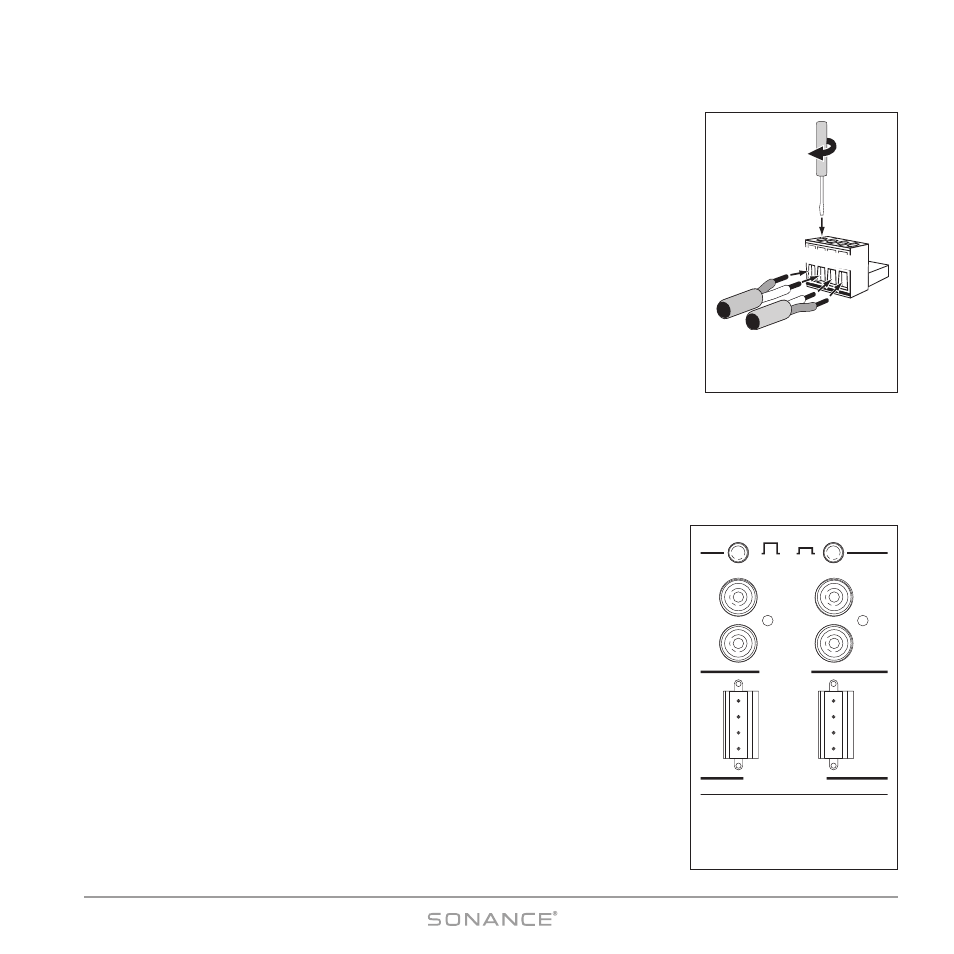
2. Strip no more than ¼” of insulation from each speaker lead. Twist the strands or tin the
exposed wire with solder to ensure that there are no stray strands. (Stray strands that
touch each other or touch the controller chassis can cause a short-circuit that can dam-
age the amplifier.)
3. The DAB1 has six removable 4-wire speaker connectors (one for each zone) that can
accept wire up to 14AWG. The connector features set screws that secure the wires.
4. Insert the exposed portions of the speaker wires into the terminal openings. Make sure
to insert the ‘+’ and ‘–’ leads into the correct openings, as shown in
Figure 6.
5. After making sure that there are no stray wires touching each other, tighten the set
screws to secure the wires, as shown in
Figure 7.
6. Press the removable connector into the corresponding zone S
PEAKER
O
UT
connector on the controller until it locks into
place (see
Figure 8).
Zone Line Output Connections
In addition to Speaker Output connectors, each zone on the DAB1 also has a set of Line Output jacks (see
Figure 8).
The Zone Line Outputs let you connect high-power amplifiers to individual zones that
require more power than the DAB1’s built-in 30 Watt/ch amplifier can provide, or expand
a zone into sub-zones by using a multi-channel amplifier.
L i n e O u t p u t F i x e d / V a r i a b l e S w i t c h
Each zone Line Output has a push-button switch that toggles the Line Output between
V
ARIABLE
(OUT) and F
IXED
(IN). (See
Figure 8.) The V
ARIABLE
setting allows zone keypad
and remote controllers to control the level of the L
INE
O
UTPUTS
. In the F
IXED
setting the L
INE
O
UTPUT
level cannot be varied.
NOT E : T h e k e y p a d a n d re m o t e c o n t r o l M
UTE
c o n t r o l s f u n c t i o n O N LY i n t h e V
ARIABLE
s e t t i n g .
II
M
MP
PO
OR
RT
TA
AN
NT
T
:: D
Do
o n
no
ott p
pu
ussh
h tth
he
e LLiin
ne
e O
Ou
uttp
pu
utt F
F
IIXXE
ED
D
//V
V
A
AR
RIIA
AB
BLLE
E
ssw
wiittcch
h w
wh
hiille
e tth
he
e
D
DA
AB
B1
1 iiss o
op
pe
erra
attiin
ng
g.. D
Do
oiin
ng
g sso
o cca
an
n p
prro
od
du
ucce
e h
hiig
gh
h o
ou
uttp
pu
utt lle
evve
ellss tth
ha
att cca
an
n
d
da
am
ma
ag
ge
e tth
he
e D
DA
AB
B1
1,, tth
he
e cco
on
nn
ne
ecctte
ed
d a
am
mp
plliiffiie
err o
orr tth
he
e ssp
pe
ea
akke
errss..
No t e : W h e n a z o n e ’ s L i n e O u t p u t i s s e t t o F
IXED
, t h e fo l l o w i n g S o n a n c e
C o n t r o l M a n a ge r Zone Setup fe a t u re s fo r t h a t z o n e a re d i s a b l e d fo r t h e
L i n e O u t p u t : Default Volume, Maximum Volume, Page Volume, Balance, Bass,
Treble. S e e p a ge s 3 2 a n d 3 3 .
VARIABLE
FIXED
OUT
IN
L
R
L
R
LINE OUT
SPEAKER OUT
8 Ω NOMINAL IMPEDANCE
34
L+
L-
R-
R+
L+
L-
R-
R+
Figure 8:
Zone Line Outputs, Speaker
Outputs and Line Output
Fixed/Variable Switches
L+L–R–R+
Use
Screwdriver
to Tighten
Set Screws
Figure 7:
Wiring the Removable
Speaker Connectors