JAI VIS-CAM System TS-1327EN User Manual
Page 91
Appendix B: J-Panel Functional & Connector Description
79
VIS-CAM System
6.10.3 Connector signal specifications
6.10.3 (a) Data signal
Ethernet signals on two pairs (Rx and Tx) .
6.10.4 Connector physical Interface
Table 32
Pin connections for Ethernet from Camera 1.
Pin Signal
Description
Connection to
1 Ethernet
A+ Ethernet
signal
Gigabit switch
2 Ethernet A-
Ethernet signal
Gigabit switch
3
Ethernet B+
Ethernet signal
Gigabit switch
4
(Ethernet C+)
Ethernet signal
Gigabit switch
5
(Ethernet C-)
Ethernet signal
Gigabit switch
6
Ethernet B-
Ethernet signal
Gigabit switch
7
(Ethernet D+)
Ethernet signal
Gigabit switch
8
(Ethernet D-)
Ethernet signal
Gigabit switch
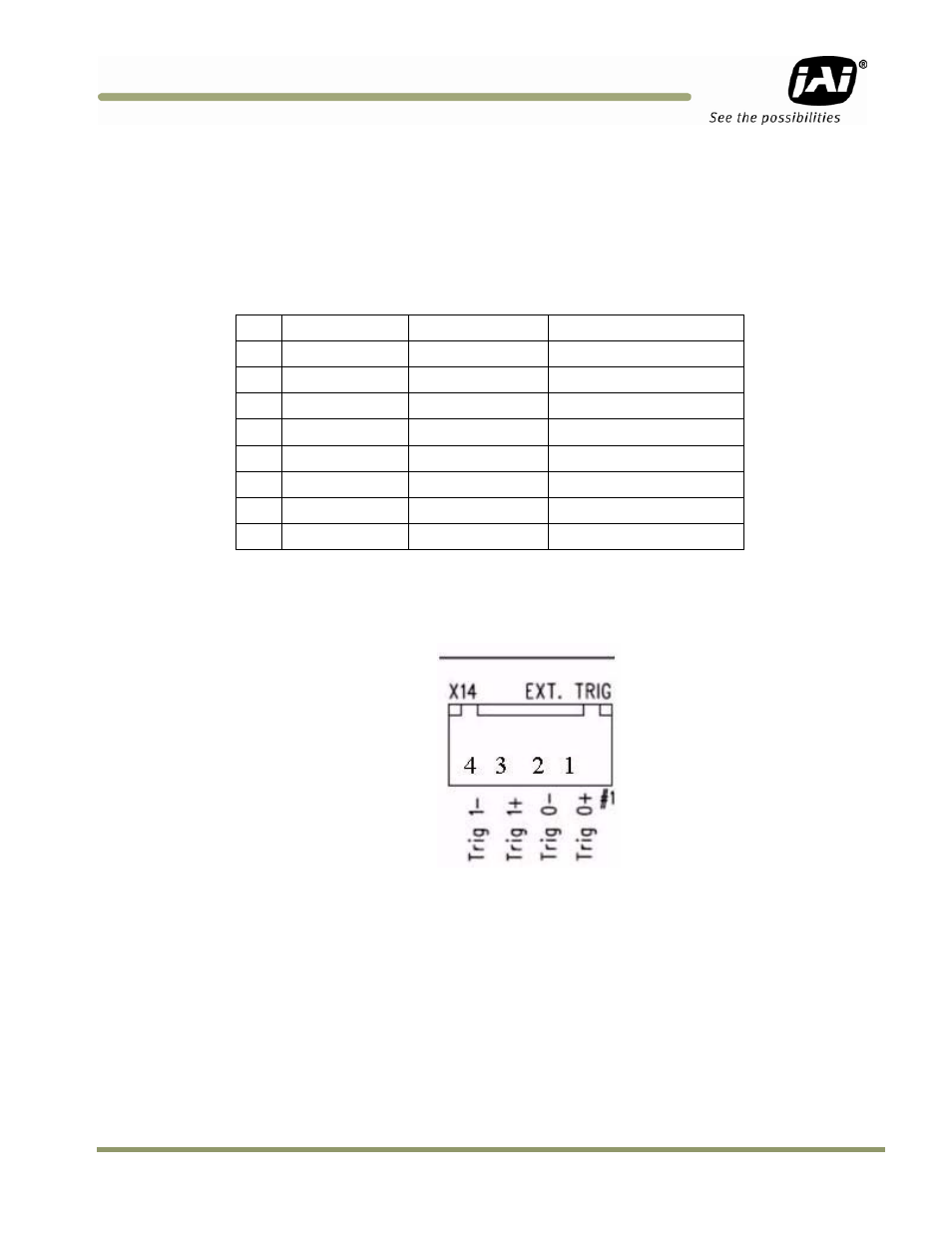
6.11 X14: External Trigger
Figure 79. External Trigger connection.
6.11.1 Functionality
The trigger inputs on the J-Panel are galvanically isolated by optocouplers in the input. The trigger
polarity can be selected on S3 and S5. Push button switches S1 and S4 are found for generating test
trigger pulses. The presence of a trigger pulse is indicated on the green LED’s marked TRIG-0 and
TRIG-1.