JAI VIS-CAM System TS-1327EN User Manual
Page 38
VIS-CAM System
26
Installing the Vehicle Imaging Subsystem
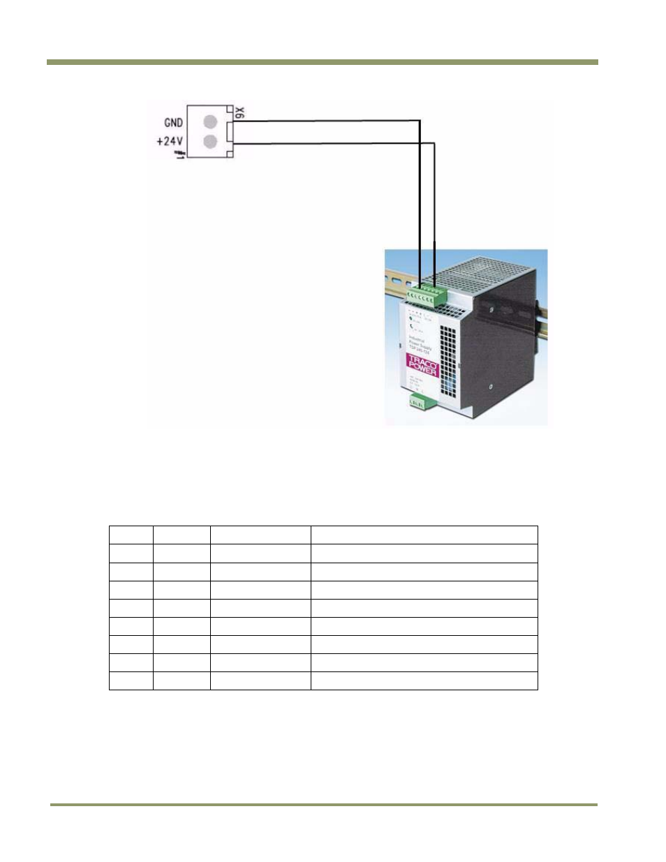
Figure 22. X-6 Power input connection.
3.3.4 X8 LS RS485 Out Connector
The RS485 output from the Light Sensor to the RS485-to-Ethernet converter connector is X8. The
connections from X8 to the converter are shown in Table 6 and Figure 23
Table 6
X8 to converter connector
X8 Pin # Signal
Description
Connection to RS485-to-Ethernet converter
1
+24V dc
24V Power output
V+ power input
2 Gnd Power
return
V- power input
3
+12V dc
12V Power output
4 Gnd Power
return
5
D0+
RS485 databus D0+
D+ Port 2
6
D0-
RS485 databus D0-
D- Port 2
7
D1+
RS485 databus D1+
D+ Port 1
8
D1-
RS485 databus D1-
D- Port1
This manual is related to the following products: