JAI VIS-CAM System TS-1327EN User Manual
Page 64
VIS-CAM System
52
Appendix A: Camera Functional & Connector Description
5.3.5 Typical Wiring Diagram
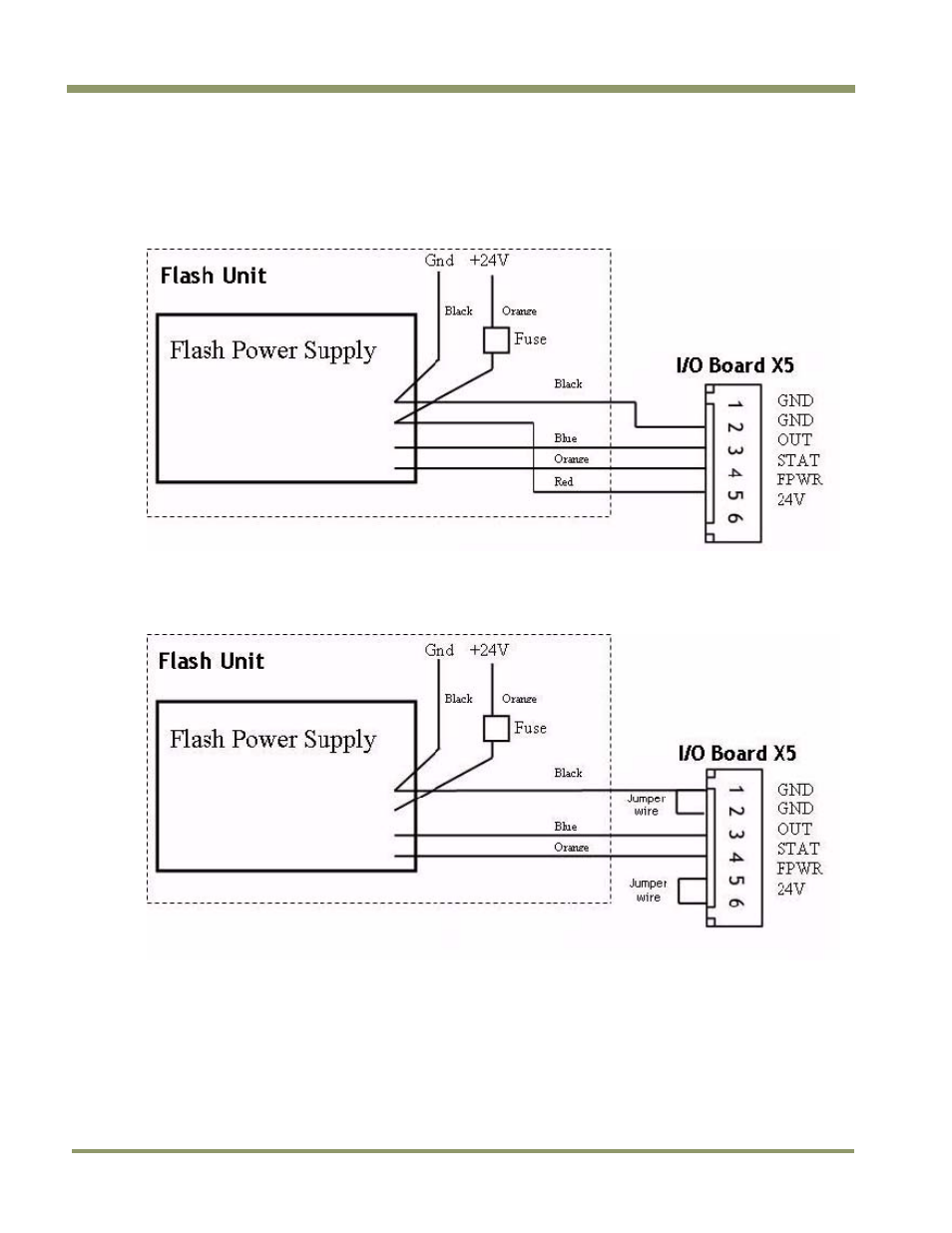
Figure 47 shows how to connect to the DC Flash unit having the I/O Board electronics powered from
the Flash Power Supply.
Figure 47. Connecting DC Flash to a board powered from the Flash power supply.
Figure 48 shows how to connect to the DC Flash unit with the I/O Board electronics internally
powered.
Figure 48. Connection DC Flash to an internally powered board.
Figure 49 shows how to connect to the AC Flash unit. Flash Power connections not shown.
This manual is related to the following products: