JAI VIS-CAM System TS-1327EN User Manual
Page 66
VIS-CAM System
54
Appendix A: Camera Functional & Connector Description
5.3.8 Connector specification
Connector type:
4 pole WAGO pluggable terminal block
Connector on board:
WAGO 734-234
Cable part:
WAGO 734-204
5.3.9 Connector signal specifications
Description
A 5V logic inverter drives the output. The inverter is a HCMOS type 74AHC14.
Output signal specification:
Signal amplitude
5V TTL
Output impedance
100 Ω
Pulse width
5 ms ± 1 ms
Signal polarity
active high
External power requirement
Voltage 8-26Vdc
Current max
25mA
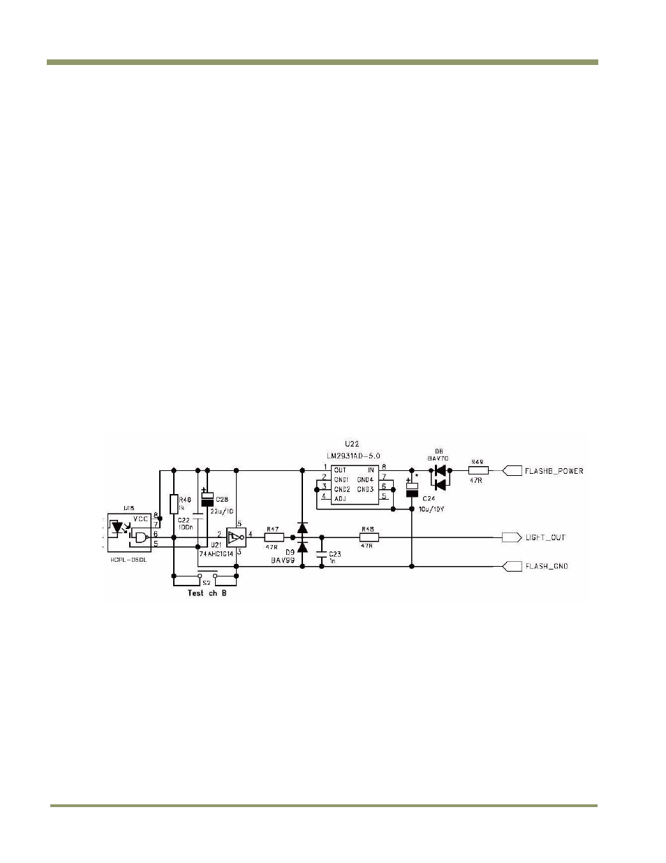
Electrical interface on the I/O board:
Figure 51. IO board electrical interface.
Test
A push button switch S2 can be activated to generate an output pulse for test purposes. The
light/flash 2 output is high as long as the switch is activated. The switch is located as shown on
Figure 51: