JAI VIS-CAM System TS-1327EN User Manual
Page 80
VIS-CAM System
68
Appendix B: J-Panel Functional & Connector Description
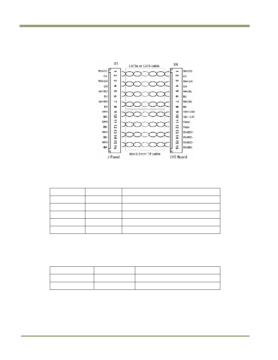
6.2.5 Typical Wiring diagram
Figure 66. Ethernet wiring diagram.
6.2.6 Indicators
There are two LED indicators mounted by the connector:
Table 19
LED indicators
LED label
LED color
Indication
Trig-0 Green Indicates
generation of trigger pulse to camera
Off
No trigger pulse
LC DATA
LED not mounted
Power
Green
24V present at connector pin 10
red
No 24V at connector pin 10
6.2.7 Switches
There are two switches located at the connector:
Table 20
Switch labels
Switch label
Switch color
Function
S4 TRIG CAM-0
Push bottom
Generates a trigger pulse to the camera
S3 TRIG POLARITY
Slide
Selects trigger polarity
This manual is related to the following products: