JAI VIS-CAM System TS-1327EN User Manual
Page 59
Appendix A: Camera Functional & Connector Description
47
VIS-CAM System
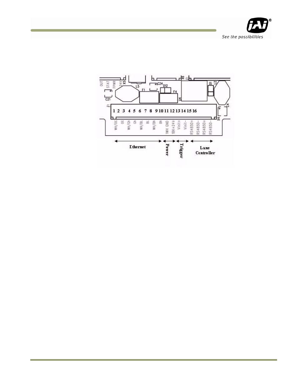
5.2 X4: I/O Board Connection to J-panel
Figure 39. Board connections
5.2.1 Functionality
Power and data connection to the camera. The 24V power supply for all camera functions (Camera,
I/O Board, light and heaters), Ethernet and RS485 data communication is connected using this
connector.
5.2.2 Connector specification
Connector type:
16 pole WAGO pluggable terminal block
Connector on board:
WAGO 734-246
Cable part:
WAGO 734-216
5.2.3 Connector signal specifications
5.2.3 (a) Lane Controller interface
Description
RS485 two wire half-duplex multi-drop communication network. The I/O Board has connections that
allow for daisy chain configuration. The two signal pairs (RS485D+ and RS485D-) can be reversed.
The signal is terminated on the J-Panel.
Signal levels:
Standard RS485 communication levels. Common mode range –7 to +12V.