Removing the i/o pcb ass'y, Removing the power sw pcb, Removing the left led and right led pcb – Matsushita CF-19FHGAX User Manual
Page 27
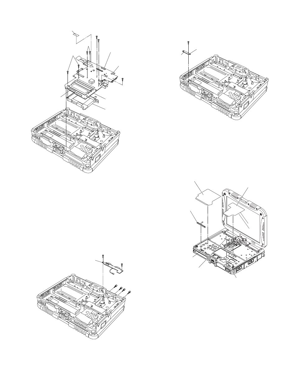
14. Remove
the 2 Screws
Holder.
15. Remove
the Tape.
16. Disconnect
the 3 Cables from the 3 Connectors.
(CN9,CN14,CN23)
17. Remove
the 7 Screws
and
Combo Socket.
Screws
Screws
Screws
Screws
9.1.10.
Removing
the I/O PCB Ass'y
1. Remove
the 4 D-SUB Screws
2. Remove
the 2 Screws
3. Remove
the I/O PCB Ass'y.
Screws
Screws
9.1.11.
Removing
the Power SW PCB
1. Remove
the Screw
2. Disconnect
the Cable from the Connector (CN9).
3. Remove
the Power SW PCB.
Screw
9.1.12.
Removing
the left LED and right
LED
PCB
1. Remove
the two Release Papers.
2. Disconnect
the Cable from the Connector (CN806).
3. Remove
the left LED PCB.
4. Disconnect
the Cable from the Connector (CN801).
5. Remove
the right LED PCB.
Tape
Main
PCB
Combo
Socket
Connector(CN9)
Connector(CN14)
Connector(CN23)
I/O
PCB Ass'y
Connector(CN9)
Power
SW
PCB
Release
Paper
Release
Paper
left
LED PCB
right
LED PCB
Connector(CN801)
Connector(CN806)