Matsushita CF-19FHGAX User Manual
Page 26
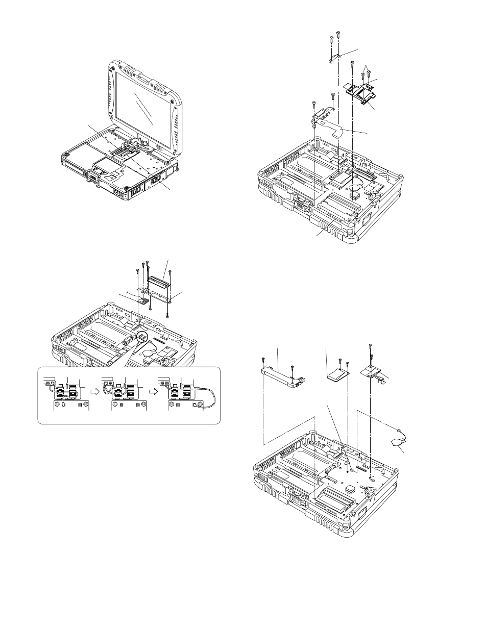
9.1.9.
Removing
the Main PCB, Wireless
Module,
SD PCB, Antenna PCB and
Modem
PCB
Note:
This
procedure is not necessary if the computer is not
equipped
with Wireless Module or Modem PCB.
1. Disconnect
the 2 LCD Cables. (CN8,CN17)
2. Remove
the gray, black and white Antenna Cables.
3. Remove
the 2 Screws
4. Remove
the 2 screws
Plate
and Antenna PCB.
5. Remove
the 2 Screws
nector
Guide.
6. Remove
the 2 Screws.
7. Disconnect
the Cable from the Connector. (CN15)
8. Remove
the BAT FPC Ass'y.
9. Remove
the 3 Screws.
10. Disconnect
the Cable from the Connector (CN21), and
remove
the SD PCB Ass'y.
11. Disconnect
the Cable from the Connector (CN3), and
remove
the Coin Battery.
12. Remove
the 2 Screws
Module.
13. Remove
the 2 Screws
PCB.
Connector(CN8)
Connector(CN17)
Plate
Antenna
PCB
DU
PCB
gray
cable
black
cable
white
cable
HDD
Connector
Guide
SD
PCB Ass'y
Connector
(CN882)
BAT
FPC Ass'y
Connector(CN15)
Connector(CN3)
DIMM
Holder Wireless Module
Modem
PCB
Coin
Battery