4 v.35 shunt procedure, Cabinet mounting screw, Link connection – Multi-Tech Systems MTASR1-100 User Manual
Page 30: Rs232/v.35, Procedure
MTASR1-100 Owner’s Manual
30
5
Connect an RS232 or V.35 interface cable to the RS232/V.35 connector on the back panel of the
RouteFinder
100
. Connect the other end of the cable to the RS232 or V.35 connector on the external link
device (modem, DSU, or ISDN terminal adapter).
V.35 requires a special cable that has a 25-pin female connector on one end and a 34-pin winchester
male connector on the other end. Refer to Appendix A for cable details.
Figure 3-5. Link Connection
The RouteFinder
100
installation is complete, proceed to Chapter 4 - Software Loading and Configuration.
3.4
V.35 Shunt Procedure
Table 3-2 provides the procedure for moving the link shunt when the RouteFinder
100
is being connected to an
external composite link device with a V.35 interface.
V.35 Shunt Procedure
Step
Procedure
1
Ensure that the external power supply is disconnected from the RouteFinder
100
.
2
Turn the RouteFinder
100
up-side-down and remove the cabinet mounting screw in the cabinet.
Figure 3-6. Cabinet Mounting Screw
3
Turn the RouteFinder
100
right-side-up and tilt the back down slightly and the base will slide out of the
cabinet.
4
Place the unit with the LEDs facing you.
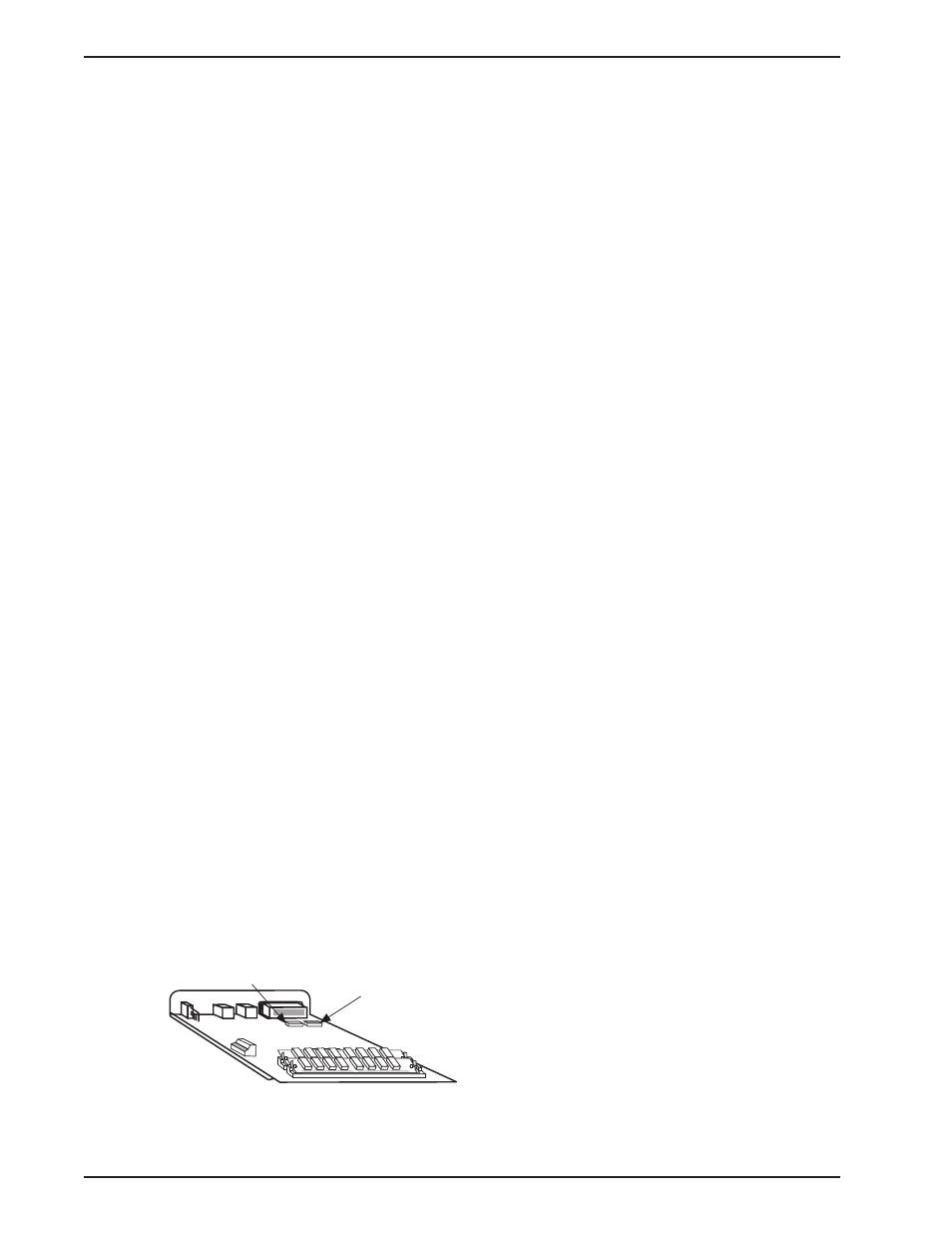
5
Pry the shunt out of the RS232 position for the link being changed and insert it in the V.35 position for that
link.
RS232
Shunt Position
V.35
Shunt Position
Figure 3-7. V.35 Shunt