2 combo board diagram, Teampos 3000 xl and xl – FUJITSU TeamPoS 3000 XL User Manual
Page 172
TeamPoS 3000 XL and XL
2
Maintenance
D900000145
Issue 3
7-39
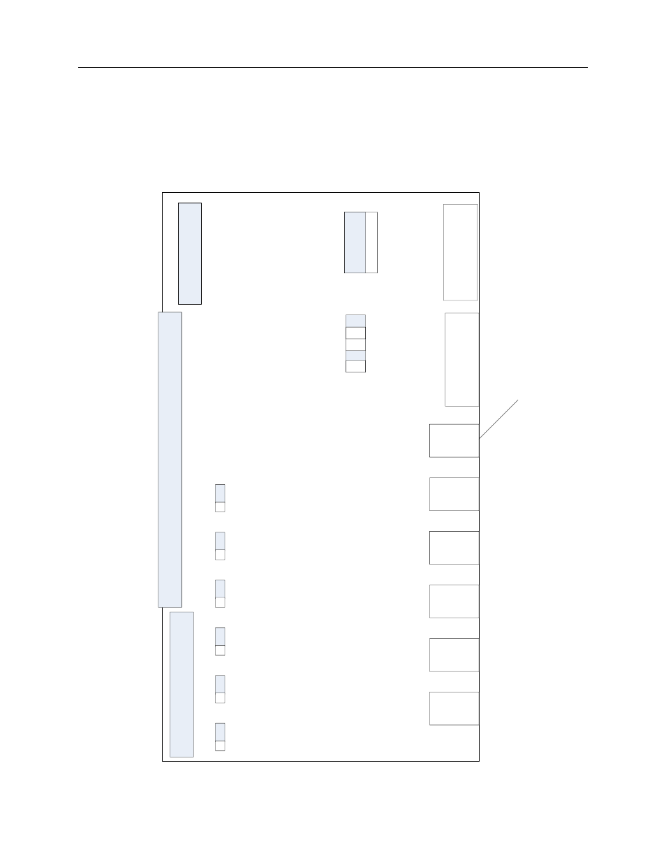
7.9.3.2 Combo Board Diagram
The following illustration shows the TeamPoS 3000 XL and XL
2
COM IN
COM OUT
UBS IN
COM
3
COM
4
P-USB6
(12V)
P-USB5
(12V)
P-USB4
(12V)
P-USB3
(12V)
P-USB2
(12V)
P-USB1
(12V)
1
1
1
1
1
1
JP
1
JP
2
JP
3
JP
4
JP
5
JP
6
PW
4
PRT
1
-7
1
2
9
10
1
3
USB signals not
available from
this port on XL
2
Combo Board and the
coinciding jumper configurations.