FUJITSU DL6600Pro User Manual
Page 68
Continuous Forms
User’s Manual
7-5
PAPER
SPECIFICATIONS
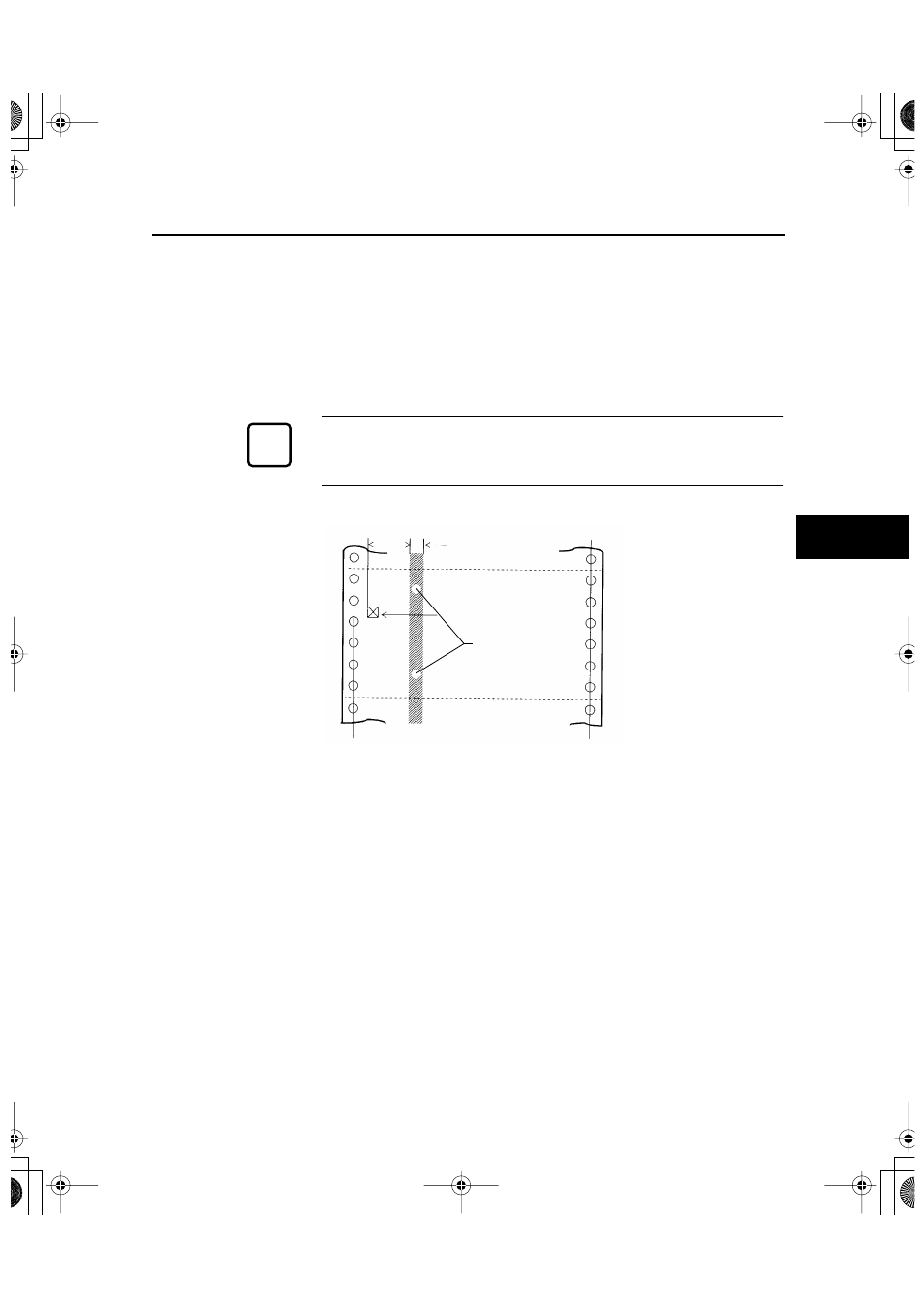
4. Binding holes in the scanning area of the sensor
The shaded area shown in the figure indicates the scanning area of
the sensor in which binding holes may lie. Their size is subject to
the following restrictions as described and illustrated.
Any binding hole completely in the shaded area must be 7 mm
(0.28 in) or less in diameter.
Caution:
Always avoid printing on the binding holes. This could damage the
print head.
5. Perforations
The perforations in continuous forms must meet the following
conditions:
The ratio of cut to uncut areas for single-part continuous forms
must be 3:1.
☞
30 mm
(1.2 in)
First character
10 mm (0.4 in)
Binding holes
DL6400/6600 Book Page 5 Thursday, September 21, 2000 7:52 PM