Figure 5 – Kramer 4 x 4 Seamless AV Matrix Switcher/Multi-Scaler User Manual
Page 19
12
VSM-4x4A
–
Connecting and Operating the VSM-4x4A
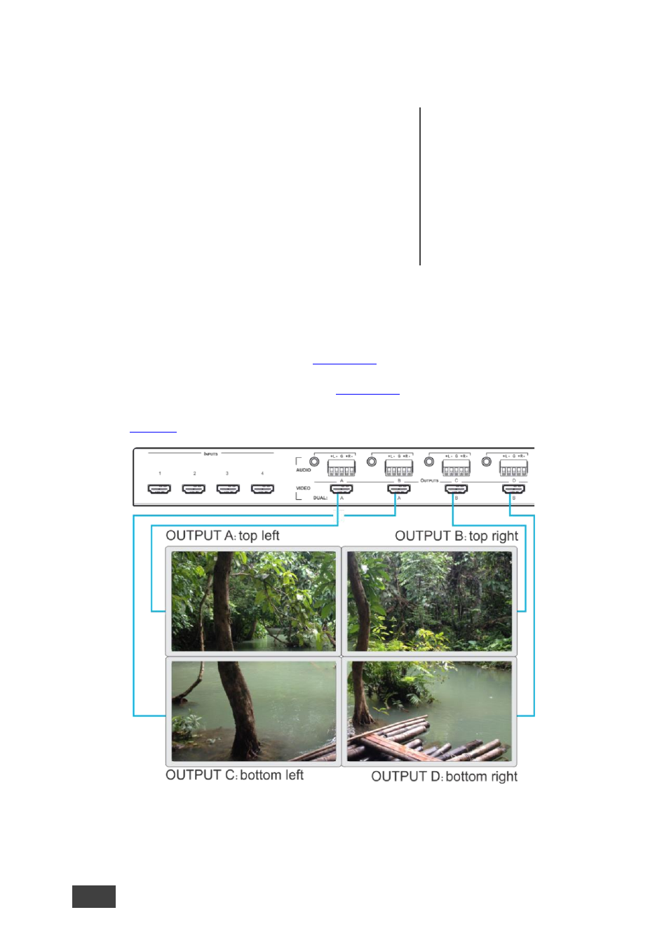
2. Connect the HDMI output connectors to the video wall screens, as follows:
For a 2x2 setup, connect:
▪
OUTPUT A to the top left screen
▪
OUTPUT B to the top right screen
▪
OUTPUT C to the bottom left screen
▪
OUTPUT D to the bottom right screen
For a 1x4 setup, connect
OUTPUT A to the top
screen, outputs B and C
below in sequence, and
OUTPUT D to the lowest
screen.
3. Connect the power cord.
4. If required, connect:
▪
A PC via RS-232, see
Section 6.3
▪
The ETHERNET port, see
Section 6.4
shows a 2x2 video wall layout:
Figure 5: Connecting the VSM-4x4A in 2x2 Video Wall Operation Mode