4 rear panel connections – BNC 7000 Series User Manual User Manual
Page 8
8
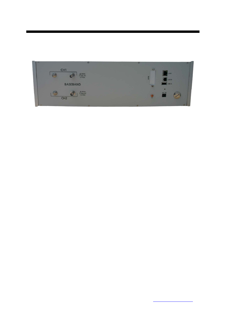
1.4 Rear Panel Connections
In Figure 2 the rear panels is shown.
Figure 2 Rear Panel View
Channel 1 and 2:
SUPPLY connector (SERIES 7000 and SERIES 7000
only)
This female BNC connector is
the programmable low-noise DC supply voltage output. Output voltage range is 0 V to +5 V,
maximum available current is 80 mA.
BASEBAND IN connector
This female BNC connector is the baseband signal input. To make
baseband noise measurement mode useful for power supply noise measurement, this port is
well protected for DC voltage application. The maximum allowed DC level is +/- 15 V.
LAN connector (8 Pin)
This RJ-45 Host connector is used for connecting via Ethernet with a
controller, such as a PC or Laptop. 10Base-T/100Base-T Ethernet (automatic data rate selection).
USB B connector
Used for connecting with a controller such as a PC or Laptop. Communication is
via USBTMC protocol. Through this port, you can control the SERIES 7000 from external controllers.
For more information on the measurement system using the USB port, see the programmer’s manual.
USB A connector
Used for connecting USB devices such as Memory sticks.
DC IN power r
ece
ptacle
The power receptacle accepts a two-pin plug from the external 6 V DC
power adapter.
GPIB (optional) connector
The connection of an external controller through General Purpose
Interface Bus (GPIB) connector allows you to configure an automatic measurement system.
Berkeley Nucleonics Corporation 2955 Kerner Blvd., San Rafael, CA 94901
Phone: 415-453-9955, Fax: 415-453-9956, Email: [email protected], Web: