2 options, 3 front panel overview – BNC 7000 Series User Manual User Manual
Page 6
6
• Universal LAN and USB 2.0 interface
• 24 months calibration cycle
1.2 Options
The following options are available for the SERIES 7000 signal analyzer:
GPIB:
GPIB interface added
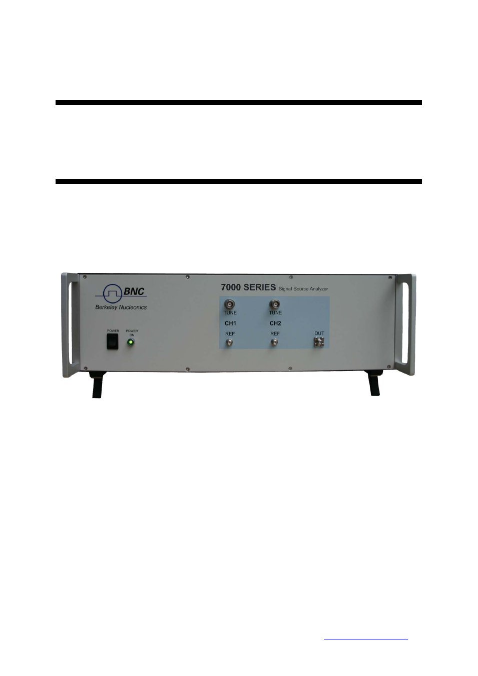
1.3 Front Panel Overview
Depending on the SERIES 7000 product configuration, the front panel can contain up to five female
SMA connectors and two female BNC connectors. A green LED indicates the power on/off status of
the instrument. Figure 1 shows the front panels of the SERIES 7300..
Figure 1 Front Panel View of MODEL 7300
DUT/RF IN connector
This female SMA connector is the DUT signal input. The input is AC-coupled
and the impedance is 50 ohm. The damage level is +26 dBm maximum. The maximum allowed DC
level is +/- 10 V.
Channel 1 and 2:
REF IN connector
This female SMA connector is the reference LO input. The impedance is
50 ohm. The damage level is +20 dBm. The maximum allowed DC level is +/- 10 V.
REF OUT connector
(SERIES 7000 ONLY) This female SMA connector is the reference LO
output. The impedance is 50 ohm. In standard operation with internal references the REF
OUT is connected by a short semi-rigid cable to the REF IN.
Berkeley Nucleonics Corporation 2955 Kerner Blvd., San Rafael, CA 94901
Phone: 415-453-9955, Fax: 415-453-9956, Email: [email protected], Web: