Piping, Mounting the controller – ITT S-DRIVE IM213 User Manual
Page 8
8
Piping
Section 4
(continued)
The pressure sensor cable is prewired to the controller. The cable can be shortened for a cleaner installation.
Longer cable lengths are available, consult factory. Maximum recommended pressure sensor cable length is
300ft. Avoid leaving a coil of pressure sensor cable as this can induce unwanted transient voltages and noise
into the system. Do not run the pressure sensor cable alongside the input or output wiring. Maintain a distance
of at least 8” between the pressure sensor cable and input or output wiring.
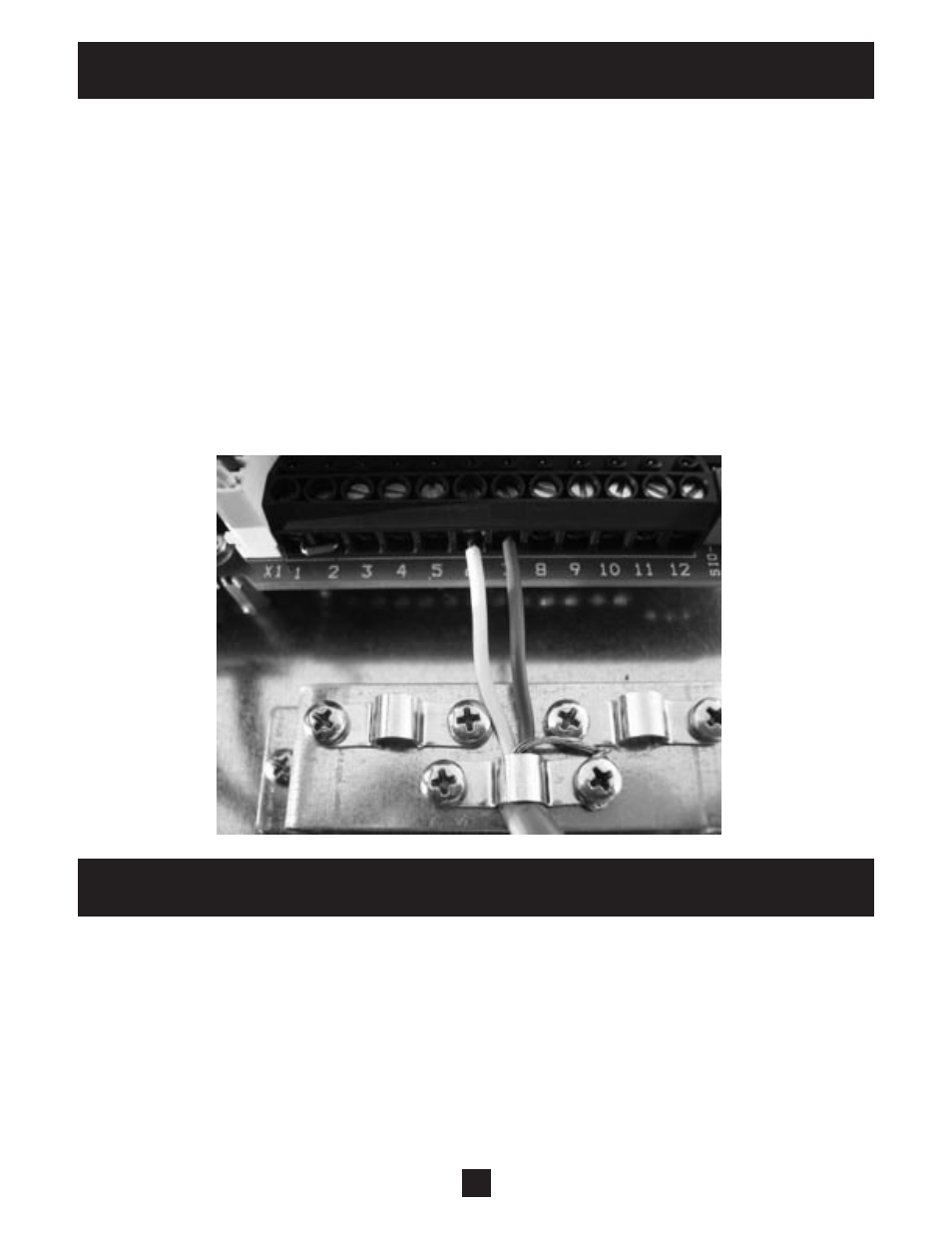
Ensure the pressure sensor cable is connected as follows: Brown to terminal 7 (24VDC SUPPLY), White to
terminal 6 (TRANSDUCER INPUT), Drain to chassis. Connecting the Drain wire to the chassis electrically
connects the sensor case to the chassis of the controller. In some cases this drain wire must be disconnected
from the controller chassis. In cases where the there is grounded metal piping which is continuous between
the transducer and the motor or the transducer is installed in grounded metal piping, a ground loop can result
so the drain wire must be disconnected from the chassis. In cases where there are sections of nonmetallic
piping between the transducer and motor or the transducer is installed in ungrounded piping this drain wire
should be connected to the controller chassis.
Mounting the Controller
Section 5
General
Mount the controller in a well ventilated, shaded area using 4 screws. The controller must be mounted
vertically. Be sure to leave 8 inches of free air space on every side of the unit. The controller must be in an
area with an ambient between -22º F and 122º F. If installation is above 3300 feet above sea level, ambient
temperatures are derated 1% per 330 feet above 3300 feet.
The altitude limit for this controller is 6500 ft.
Do not install above 6500 ft.