Power supply and wiring, Conduit, wire and fuse sizing, Generator sizing – ITT S-DRIVE IM213 User Manual
Page 13: Continued)
13
Power Supply and Wiring
Section 6
(continued)
Conduit, Wire and Fuse Sizing
The use of metal conduit with metal conduit connectors is recommended for all electrical connections. Use the
NEC or CEC to determine the required conduit size for the application.
Refer to the chart below for the minimum allowable wire size for each controller. Note that these wire sizes
are not adjusted for voltage drop due to long cable lengths. Refer to the wire sizing chart in the appendix to
determine the maximum length for the input cable. Refer to the motor manual for maximum output cable
length. The maximum recommended voltage drop on both input and output cable combined is 5%. Standard
wire sizing charts give maximum cable lengths for only input or output cables. Because of this the lengths
given in the table must be adjusted so the total voltage drop does not exceed 5%. For example, if the input
wire sizing chart in the appendix gives the maximum length of 400' and only 100' is used then only 25% of the
total voltage drop (1.25% drop) is used. The maximum output cable length read from the motor‘s wire sizing
chart must then be adjusted to 75% of its value so that the maximum voltage drop of 5% is not exceeded.
Use only fast acting class T fuses. The wire used for the input power connections on models SPD20300 and
SPD20300F must have a temperature rating of 90ºC minimum. All other wire must be rated 75 ºC minimum.
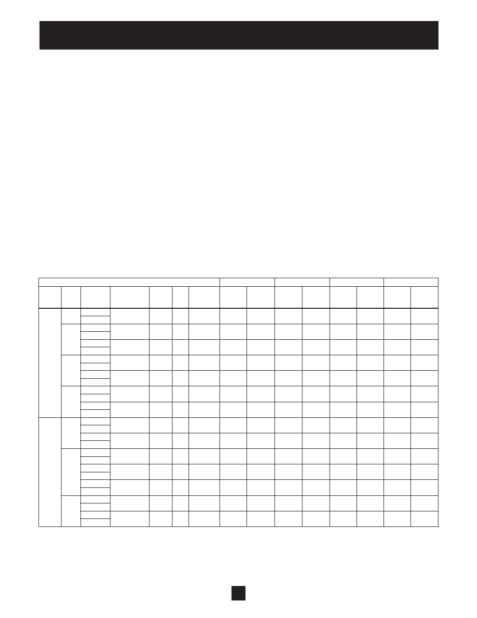
The chart below shows the recommended sizes for wire and fuses for each controller. Note that the wire sizes
were not adjusted for voltage drop due to long cable lengths.
Maximum Ambient Temperature ➞
20ºC 30ºC 40ºC 50ºC
Generator Input Output Input Output Input Output Input Output
Voltage
Frame
Model Full
Load Nominal
Fuse Size Cable Cable Cable Cable Cable Cable Cable Cable
Size
Number Output Current
HP
Size
(VA)
Min. AWG Min. AWG Min. AWG Min. AWG Min. AWG Min. AWG Min. AWG Min. AWG
1
SPD20050
17.8 5.0
30.0
7700 10 14 10 14 10 12 8 12
SPD20050F
SPD20075
26.4 7.5
40.0
11400 8 12 8 10 8 10 6 8
2
SPD20075F
SPD20100
37.0 10.0
50.0
16000
8 10 8 8 6 8 4 8
SPD20100F
SPD20150
47.4 15.0
70.0
20500
4 8 4 8 4 6 3 6
230
3
SPD20150F
SPD20200
60.6 20.0
80.0
26200
4 6 4 6 4 4 2 4
SPD20200F
SPD20250
76.0
25.0 110.0
32800
2
4
2
4
1
3
1/0
2
4
SPD20250F
SPD20300
94.0
30.0 135.0 40600
2* 3 1* 3 1* 2 1/0* 1
SPD20300F
SPD40050
8.9 5.0
15.0
7700 14 14 14 14 14 14 14 14
1
SPD40050F
SPD40075
13.2 7.5
20.0
11400 12 14 12 14 12 14 10 14
SPD40075F
SPD40100
18.5 10.0
30.0
16000 10 14 10 14 10 12 8 12
SPD40100F
460
2
SPD40150
23.7 15.0
40.0
20500 8 12 8 12 8 10 6 10
SPD40150F
SPD40200
30.3 20.0
50.0
26200 8 10 8 10 6 10 4 8
SPD40200F
SPD40250
37.5 25.0
60.0
32400
6 8 6 8 4 8 4 8
3
SPD40250F
SPD40300
47.0 30.0
70.0
40600
4 8 4 8 4 6 3 6
SPD40300F
* 90ºC Wire Required on input to controller.
Generator Sizing
Refer to the chart above to determine the minimum generator size for each controller.