Troubleshooting – ITT S-DRIVE IM213 User Manual
Page 22
22
Troubleshooting
Red Light Codes (continued)
Flashes
Controller Status
Description
3 Blinks (contd.)
- Disconnect the White wire in the sensor cable from terminal 6.
- Set the meter to read DC current (mA)
- Connect the black lead from the meter to terminal 6
(TRANSDUCER INPUT)
- Connect the red lead from the meter to the White wire in the
sensor cable.
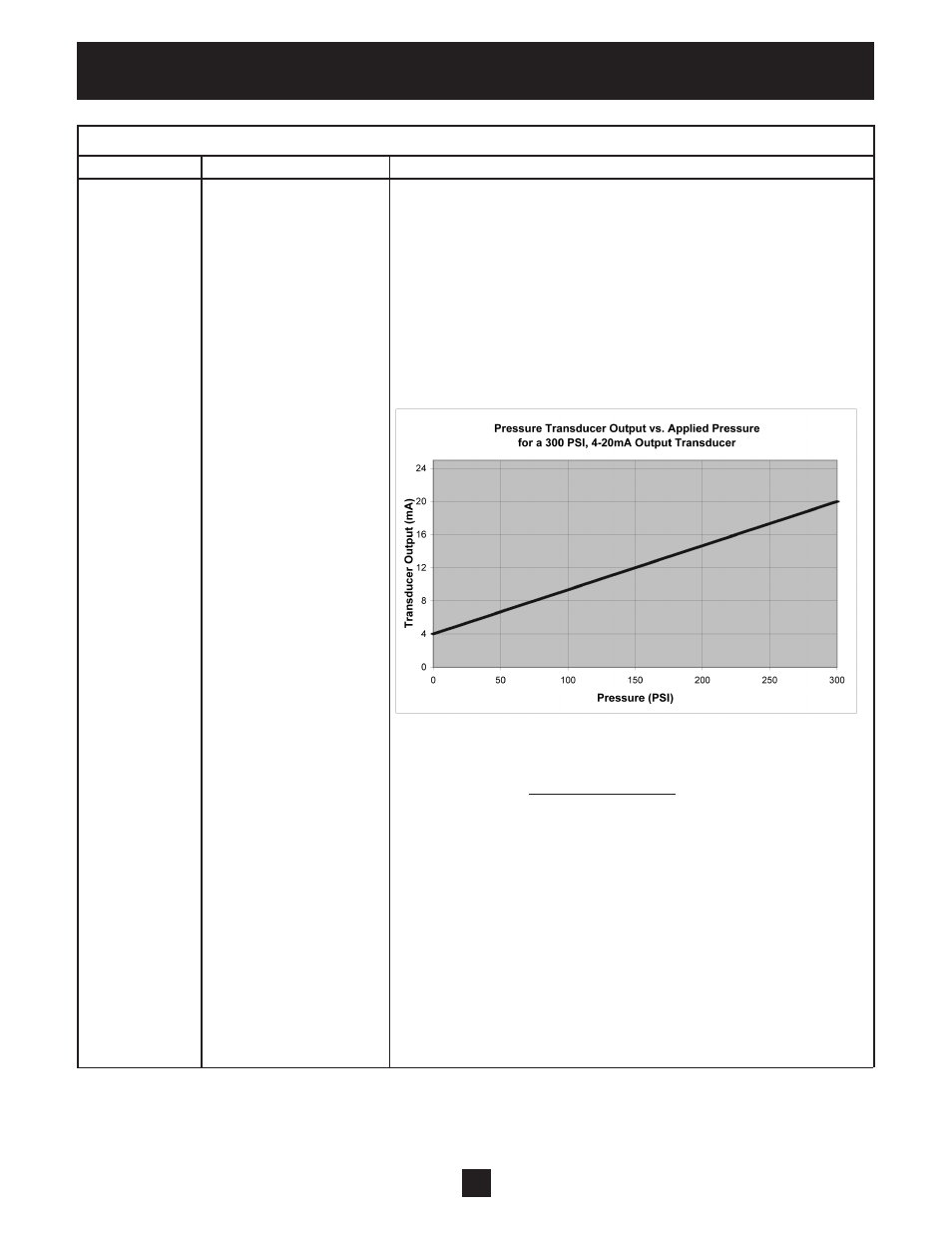
- The meter will display the output of the sensor. If functioning
properly, the output of the sensor will be between 4mA and
20mA depending on the pressure in the system. Refer to the
chart below to determine the sensor feedback at various pressures.
The following formula gives the transducer output based on applied
pressure:
Output Current = Output Current Range x System Pressure + 4mA
Pressure Range
Where:
• Output Current is the transducer output
• Output Current Range is the maximum output signal of the
transducer minus the minimum output signal of the transducer. In
this case:
Output Current Range = 20mA – 4mA, or 16mA
• Pressure Range is the pressure that corresponds to the maximum
output signal. For a 300 PSI transducer the Pressure Range =
300 PSI – 0 PSI = 300 PSI
• System Pressure is the system pressure as read on the pressure
gauge.
[
]
(
)